The KX2 hard buttons compatible with the RTI Laser Shark custom button
etching program - nd details on the rticorp.com dealer section.
REMOVING BUTTONS
1. Remove the KX2 bezel.
2. Using a ngernail or small
screwdriver, gently pry up
on the removal tabs along
outer edge of the button.
INSTALLING BUTTONS
1. Place the button at an angle
into the button location,
inserting the “alignment
tab” into the KX2 rst.
2. Gently press down on the
outer edge of the button
until it snaps into place.
The KX2 is designed for ush-mount, in-wall installations.
MOUNTING HEIGHT
The recommended mounting height for the KX2 is between 54 inches (1.37m)
and 60 inches (1.52m) from the bottom of the faceplate.
USING MOUNTING WINGS
Two mounting wings are located on the top and bottom of the KX2, which can be
used to secure the KX2 to drywall in retrot installations.
1. Use the included cardboard cut-out template to create the correct size
opening in the wall.
2. Place KX2 in the opening in the wall and tighten the mounting wing screws
located on the front of the KX2 (bezel removed).
USING CONDUIT/BACK BOX
The KX2 uses a standard 4”x 4” electrical junction box. These should be
available at most hardware stores or online electrical supply stores
(ex. Granger.com).
IMPORTANT NOTES:
• A dual gang outlet box will NOT work.
• The KX2 has .38” thick corner tabs, making the
KX2 protrude .38” from the front edge of the
junction box. Therefore, the electrical box should
be mounted ush with the wall stud. Typically
wall sheeting materials like drywall are ½” or
thicker, allowing the KX2 to be ush with the
wall sheeting. If the wall sheeting is thinner than
.38”, the junction box will need to be mounted
set back.
• Use #8 – 32 at head screws.
• Box should be 1.5” minimum depth.
Cutout (WxH): 3.789”(96.5mm) x 3.789”(96.5mm)
Bezel (WxH): 4.6”(117mm) x 4.4”(112mm)
Depth In-Wall: 1.2”(30.5)
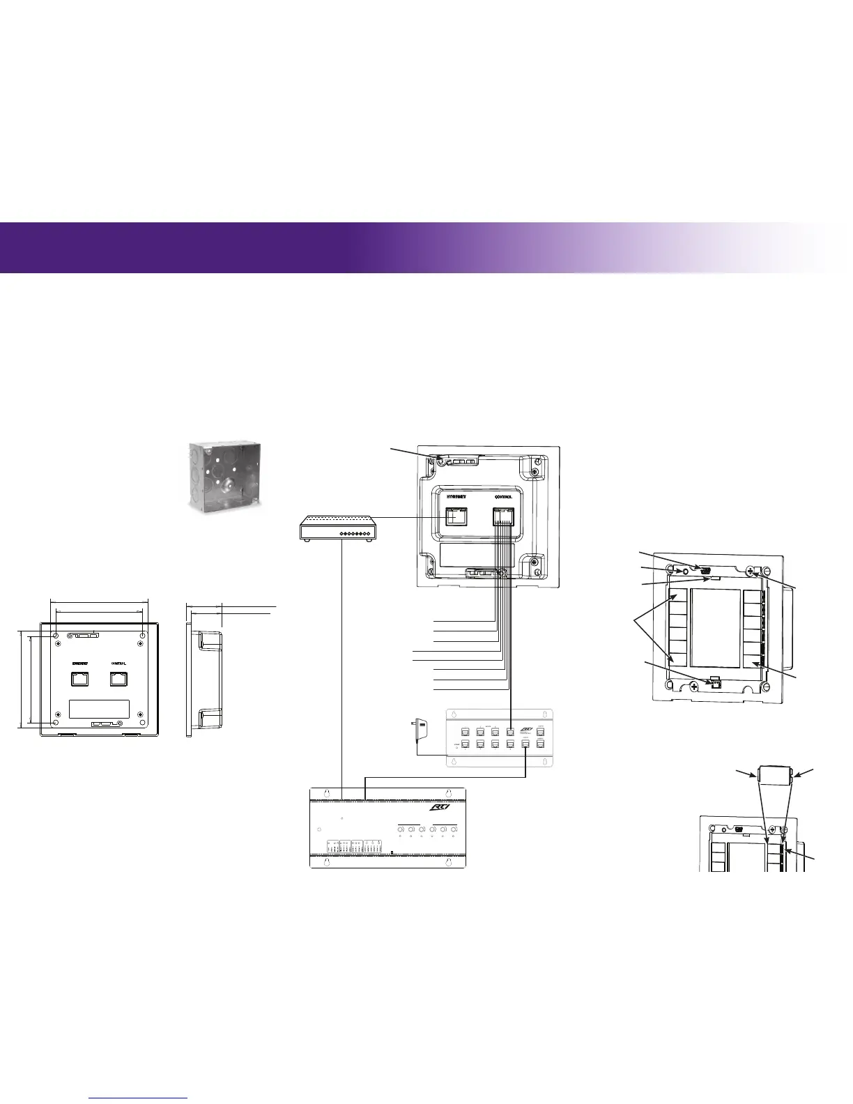
1) CB8 Connecting Block: Wire a Cat-5 cable from the KX2 Control Port to
the CB8 Connecting Block (see diagram).
2) Ethernet Port (Power over Ethernet): Wire a Cat-5 cable from the KX2
Ethernet Port to an 802.3af compliant Power-over-Ethernet router/switch
(Class #2).
NOTE: Using a non-compliant PoE device may damage the KX2.
3) Power Supply: Connect a power supply (+9VDC to +16VDC, .5A ) to the
“Ground” and “9-16VDC” pins of the Control Port (see diagram).
NOTE: The KX2 should NOT be powered from an RTI control
processor.
It’s Under Control
®
CONNECTIONS
CONTROL PORT
The Control Port on the KX2 uses a Cat-5 cable with RJ-45 termination. When
used in conjunction with an RTI control processor (e.g. RTI XP-6) and an RTI
connecting block (e.g. RTI CB-8), this port serves as the power source for
the KX2 in addition to infrared and RS-485 communication (see diagram for
pinout).
ETHERNET PORT
The KX2 Ethernet Port is designed for connection to an Ethernet network (LAN)
via Cat-5 cabling with RJ-45 termination. Additionally, the KX2 can be optionally
powered using Power-Over-Ethernet, allowing the power to be extended to the
KX2 over the same Cat-5 cable that carries Ethernet communication. When
powering the KX2 using PoE, a 802.3af compliant Power-over-Ethernet router/
switch (Class #2) must be used or damage to the unit may occur.
USB PORT
The KX2 USB port (located on the front of the unit beneath the bezel) is used to
update rmware and the programming data le using a USB-A to Mini-B cable.
POWERING THE KX2
The KX2 has many settings that can be adjusted directly through the control
panel. Please note that changes made directly in the KX2 control panel will be
overwritten by changes made in Integration Designer.
ACCESSING THE CONTROL PANEL
The Control Panel page can be displayed by pressing and holding down the
button located in the lower right corner of the KX2 (default labelled with the
power symbol), while applying power or resetting the KX2.
ADJUSTABLE SETTINGS
• Backlight Level • Time Out • Sound • Proximity Sensor
• Network Information
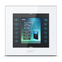
KX2
In-Wall Controller
MOUNTING
KX2 (Rear)
PROGRAMMING
CONTROL PANEL
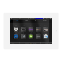
THE TOUCHSCREEN DISPLAY
The KX2 touchscreen display is programmed using the RTI Integration Designer
Programming Software. Normally it is organized into a series of pages containing
objects (buttons, text, graphics, etc.) that are related to each other. For
example, they may all display information necessary for controlling a particular
music server, room lighting, security system status etc.
UPDATING FIRMWARE
It is highly recommended that this and all RTI products have the latest rmware
installed. The rmware can be found in the Dealer section of the RTI website
(www.rticorp.com). Install the rmware using a USB cable (USB A to Mini B).
UPDATING SOFTWARE
RTI’s Integration Designer data les can be downloaded to the KX2 using a
USB cable (USB A to Mini B), or via the Ethernet network (LAN). If the KX2 is
hard-wired to a LAN and the router has DHCP enabled, the initial data le can be
downloaded over Ethernet.
Mounting Wings (2)
(One located on bottom
of KX2 also.)
KX2 (Front)
USB Port
Proximity and Ambient
Light Sensor
Programmable
Hard Buttons (12)
Touchscreen
“Power” Button
(Press to access
Control Panel-
see instructions)
Proximity Emitter
Reset Button
Mounting Wing
Screws (2)
HARD BUTTON REPLACEMENT
Button
Alignment
Tab
Button
Removal
Tabs
(Outer Edge)
KX2
Button
Pry up
here to
remove.
KX2 (Front)
KX2 DIMENSIONS
 Loading...