EasyManua.ls Logo

RTW PortaMonitor 1062 User Manual

Default Icon
76 pages
Go to English
To Next Page IconTo Next Page
Page #1 background imageLoading...
Page #1 background image
Handbuchversion:
Softwareversion:
Seriennummer:
RADIO-TECHNISCHE WERKSTÄTTEN GmbH & Co. KG
Fax: (02 21) 7 09 13-32 • Tel.: (02 21) 7 09 13-33
Hausadresse: Elbeallee 19 • 50765 Köln
Postfachadresse: Postfach 71 06 54 50746 Köln
Internet: www.rtw.de E-Mail: rtw@rtw.de
BedienungsanleitungBedienungsanleitung
Bedienungsanleitung
Operating manualOperating manual
Operating manual
PP
PP
P
oror
oror
or
taMonitortaMonitor
taMonitortaMonitor
taMonitor
24 V/12 V/5 V24 V/12 V/5 V
24 V/12 V/5 V
4.3 (12 V)
3.x
MAN Porta_12V

Table of Contents

Question and Answer IconNeed help?

Do you have a question about the RTW PortaMonitor 1062 and is the answer not in the manual?

RTW PortaMonitor 1062 Specifications

General IconGeneral
BrandRTW
ModelPortaMonitor 1062
CategoryMeasuring Instruments
LanguageEnglish

Summary

6. Getting started

6.2. Conneting the PortaMonitor 1061/1062

Wiring and connection details for PortaMonitor models 1061 and 1062.

6.3. Conneting the PortaMonitor 1063/1064

Wiring and connection details for PortaMonitor models 1063 and 1064.

6.4. Conneting the PortaMonitor 1064V12

Wiring and connection details for PortaMonitor model 1064V12.

6.5. Conneting the PortaMonitor 1064V5

Wiring and connection details for PortaMonitor model 1064V5.

6.6. Safety symbols

Explanation of safety symbols used in the manual and on the equipment.

6.7. Safety information

Essential safety precautions and guidelines for using the instrument.

6.8. Connecting to a power supply

Details on connecting the PortaMonitor to a DC power source.

6.11. Modes switches and indicators

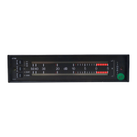
Explanation of various modes, switches, and indicators on the PortaMonitor.

7. Switches and menus

8. Calibration and Service

8.1. Calibration

Information on the device's calibration, stating no adjustments are required due to DSP technology.

8.2. Reference level change

Procedure for adjusting the input level range and reference settings.

8.3. Open the unit

Guidelines for service engineers on opening the unit for adjustments or part exchange.

8.4. Display exchange

Instructions for exchanging the display unit, including mainframe replacement.

Related product manuals