- 4 -
MOUNTING
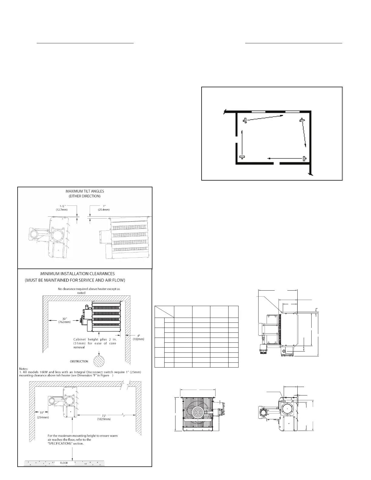
1. The heater must be permanently mounted in a level,
upright position for operation. See Figures 2, 3, and
4 for maximum tilt angles, installation clearances,
and physical dimensions. For ease of installation,
a variety of mounting kits are available from the
factory.
2. The mounting structure must be strong enough to:
a. support the heater’s weight, refer to the
“Specifications” section,
b. provide sufficient stiffness to prevent excessive
vibration, and
c. withstand harsh situations such as transportable
installations.
FIGURE 5
WARRANTY WILL BE VOID
IF INSTRUCTIONS ARE NOT FOLLOWED
INSTALLATION
The installation instructions provide a general guideline for the installation and wiring of the heater.
All applicable codes must be adhered to.
MECHANICAL
i
HEATER LOCATIONS
EXTERIOR WALL
EXTERIOR
WALL
FIGURE 2
LOCATION
For optimum heating, the heater should be installed as follows:
1. There are no obstructions that may impede the heater’s air
inlet or discharge.
2. The air discharge is directed into open areas and not at
occupants.
3. The air discharge is not directed at a thermostat.
4. The air discharge is directed across areas of heat loss, such
as doors and windows (see Figure 1).
5. The air discharge is directed along and at a slight angle
toward exterior walls (see Figure 1).
6. If equipment freeze protection is important, direct air
discharge at equipment.
7. Air discharge streams support each other and create a
circular air flow. It is not required that the heater’s air throw
reaches the next heater (see Figure 1).
FIGURE 3
FIGURE 4
5
DIM.
2.5 - 9.3 12.5 - 18.5 20.9 - 23.1
DIM.
TOL.
±
A
in 8 - 1/16 6 - 11/16 7 - 1/16 1/8
mm 204 170 179 3
B
in 8 - 3/16 22 -3/16 26 - 3/16 1/8
mm 462 564 665 3
C
in 24 - 5/8 28 - 5/8 32 - 5/8 5/16
mm 625 727 828 8
D
in 18 - 1/2 22 - 1/2 26 - 1/2 1/8
mm 470 572 674 3
E
in 19 - 7/16 23 - 7/16 27 - 7/16 1/8
mm 494 596 697 3
kW
DIMENSIONAL TOLERANCES ± 0.118” (3 mm)
UNLESS OTHERWISE SPECIFIED.
M32 OR M25 ADAPTORS
(FOR FIELD WIRING)
E
D
1.5” (38 mm) MAX.
15.7 ± 0.2”
(400 ± 5 mm)
17.2 ± 0.2”
(436 ± 5 mm)
3 ± 0.2”
(75 ± 6 mm)
B
C
0.6” (16 mm)
10.4 ± 0.2”
(263 ± 5 mm)
22.6”
(575 mm)
MAX.
Ø0.6” (Ø14.3 mm)
MOUNTING HOLE
(2 PLCS)
A