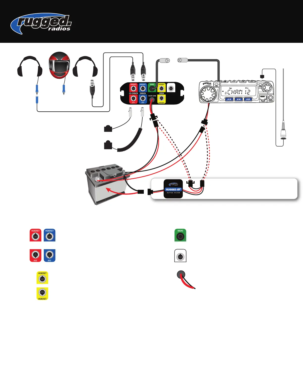
RADIO
CO-DRIVER STRAIGHT
CORD PTT
DRIVER COIL
CORD PTT
ANTENNA
If using optional Active Filter, connect radio
and intercom power leads directly to
Active Filter and NOT to the battery.
POWER
**This is a universal wiring diagram. Your exact configuration might vary depending on the system purchased.
HEADSETS connects driver and co-driver headsets
to intercom. Route away from power and antenna
cables.
RADIO connects to optional Radio.
AUX OUT audio output for sound systems for
recrding devices.
POWER connect +/- directly to 12v battery.
PUSH-TO-TALK connects driver and co-driver PTT
to intercom.
CREW connects additional headsets to intercom.
696 PLUS INTERCOM
USER MANUAL
Radio & Intercom Mounting
Both the intercom and radio come with universal
mounting brackets. Vehicle specific mounting
options are sold separately.
DO NOT mount the radio or intercom near an
ignition box to avoid RF interference.
Route antenna cable away from power leads and
headset cables.
•
•
•
Connect Power
Route all power cables directly to the battery, away from
other power/headset cables.
DO NOT connect inline with other components. If power
is tied to ignition, lights or other power sources, a ground
loop problem may occur, causing noise in the system.
DO NOT remove any fuses that are in line with factory
cables or otherwise modify power cables.
•
•
•
Rugged Radios | www.ruggedradios.com | 888-541-7223
AUX OUT
AUX OUT