Copyright © 2015 Ruckus Wireless, Inc. Page 3 of 4
Published 10 February 2015, Part Number 800-70766-001 Rev B
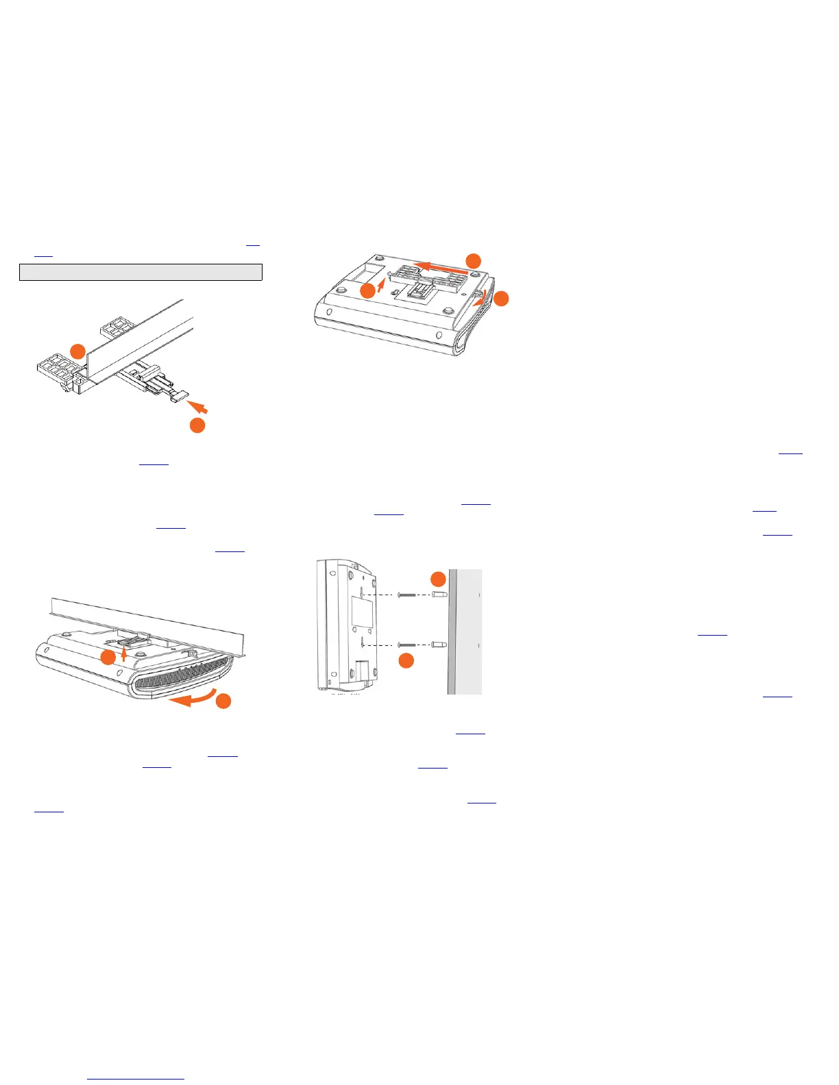
6 Hold the AP in place and gently push the locking tab (B in Fig-
ure 4) until its clasp grips the other edge of the T-bar.
Figure 4. Attaching the T-bar bracket to the T-bar
7 (Optional) Attach a customer-supplied padlock through the
bracket AP retainer tab (B in Figure 3
) to lock the AP to the T-
bar bracket studs.
When you are done, the AP is mounted.
Removing the AP from the T-bar:
1 Move the ceiling tiles, if present, out of the way.
2 Gently lift up the locking tab (A in Figure 5) by sliding your fin-
ger under the tab.
3 Rotate the AP- and-T-bar bracket assembly (B in Figure 5).
The AP- and-T-bar bracket assembly comes away from the T-
bar.
Figure 5. Removing the AP and T-bar bracket from the T-bar
Removing the T-bar bracket from the AP:
1 If the AP is locked to the T-bar bracket, then remove the lock.
2 Gently lift up the T-bar bracket locking tab (A in Figure 6) and
push the AP retainer tab (B in Figure 6
) to the side at the same
time.
3 While lifting up the T-bar bracket locking tab and pushing the
AP retainer tab to the side, gently push the T-bar bracket (C in
Figure 6
) toward the Ethernet ports on the bottom of the AP
until the bracket detaches from the AP.
Figure 6. Removing the T-bar bracket from the AP
Mounting on a Flat Surface
The factory-supplied mounting screws and plastic wall anchors
allow you to attach the AP to a wall or ceiling.
1 Use the Mounting Template on the last page of this Quick
Setup Guide to mark the locations for two drill holes on the
mounting surface. Note: There is a second set of keyholes
that are for optional sideways mounting on a flat surface.
Physical security is not supported when mounting the AP
with this set of keyholes.
2 Use a 4.75mm (3/16”) drill bit to drill holes approximately
25mm (1”) deep into the mounting surface.
3 Insert the factory-supplied anchors (A in Figure 7) and mount-
ing screws (B in Figure 7
) into the mounting surface, leaving
approximately 6 mm (1/4”) of the screw heads protruding for
the AP enclosure.
Figure 7. Flat surface mounting
4 Place the AP onto the mounting screws so that the screw
heads enter the keyholes on the AP enclosure, and push the
AP down until the AP retainer tab (B in Figure 6
) snaps into
place.
5 (Optional) Attach a customer-supplied padlock through the
integral AP retainer tab (B in Figure 6
) to lock the AP to the
mounting screw heads.
6 To remove the AP from the factory-supplied mounting screws,
push sideways on the AP retainer tab (B in Figure 6
), to unlock,
then push the AP up to release the AP enclosure from the
mounting screws.
Mounting on a Flat Surface or Pole Using the
Optional Secure Mounting Bracket
The customer-ordered Ruckus Wireless secure mounting bracket
kit (ordering part number 902-0120-0000) includes a metal
mounting bracket and provides greater security when attaching
the AP to flat surfaces (walls and ceilings) and to poles.
• If you are mounting the AP on a flat surface, then you will also
need an electric drill with a 4.75mm (3/16”) drill bit, and the
four No. 6 zinc plated screws and plastic wall anchors
included with the kit.
• If you are mounting the AP on a truss or pole, then you will
also need the two pipe clamps included with the kit.
Continue with the following:
1 If you are mounting the AP on a flat surface, then use the
secure mounting bracket as a template to mark the locations
for four drill holes on the mounting surface. There are four
screw holes available on the secure mounting bracket.
Fasten the bracket to the flat surface using four mounting
screws and plastic wall anchors and continue with Step 3
.
2 If you are mounting the AP on a pipe or pole, then feed the two
stainless steel clamps included with the kit through the slots
on the secure mounting bracket. Use common hand tools to
tighten the clamps around the pipe or pole.
After the bracket is attached, continue with Step 3
.
3 Insert the two studs on the secure mounting bracket into the
keyholes on the bottom of the AP, as shown in Figure 3
. Note:
There is a second set of keyholes that are for optional side-
ways mounting on a flat surface. Physical security is not sup-
ported when mounting the AP with this set of keyholes.
4 Slide the AP toward the Ethernet ports on the bottom of the
AP. The AP has a built-in lock for the secure mounting bracket
studs, and snaps into the locked position when the studs are
fully in the keyholes.
5 (Optional) Attach a customer-supplied padlock through the
integral AP retainer tab (B in Figure 6
) to fasten the AP to the
secure mounting bracket studs.
Removing the AP from the secure mounting bracket:
1 If the AP is locked to the secure mounting bracket, then
remove the lock.
2 Gently push and hold the AP retainer tab (B in Figure 6) to the
side to release the secure mounting bracket.
3 While holding the AP retainer tab to the side, slide the AP away
from the Ethernet ports on the bottom of the AP.
For More Information
You can now use the wireless network to log into the AP’s Web
interface. For information on how to configure the AP, refer to the
Ruckus Wireless Access Point User Guide, or refer to the
appropriate Ruckus Wireless AP controller or AP manager user
documents.
Note: Make sure that all three clasps are gripping the T-bar!
 Loading...