Do you have a question about the RVP 6536A335 Series and is the answer not in the manual?
Details the intended use and connection requirements of the 6536A335* thermostat with RV Products 2-stage heat pumps.
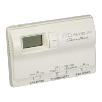
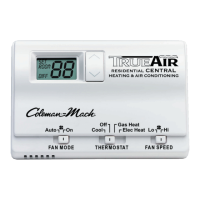
Explains the display indicators, setpoint adjustment, and operation modes like electric heat and gas heat.
Details the wiring connections required for the wall thermostat, including OEM supplied parts and lifeline connections.
Details the pinout and connections for the 9-pin thermostat plug on the printed circuit board.
Explains the operation of the indoor blower at both high and low speeds, detailing connections and signals.
Describes the operation of Compressor #1 and Compressor #2 during cooling mode, including circuit board connections and relays.
Details the function of the indoor and outdoor coil sensors, including freeze protection and LED indicator status.
Explains the operation of the outdoor blower at low and high speeds, detailing connections and signals from compressor relays.
Describes the heat pump operation in heating mode, focusing on reversing valves, indoor blower, and compressor activation.
Provides the secondary wiring diagram specifically for the 6536 'A' and 'B' series two ton packaged heat pump models.
| Brand | RVP |
|---|---|
| Model | 6536A335 Series |
| Category | Thermostat |
| Language | English |