6 — English
ASSEMBLY
NOTICE:
Failure to attach the grass deector prevents the line
being cut to the proper length and can cause tool failure.
NOTE: Install the grass deector before the attachment is
connected to the power head.
Remove the bolt from the grass deector.
Insert the tab on the mounting bracket in the slot on the
grass deector.
Align the hole in the mounting bracket with the hole in
the grass deector.
Insert the bolt through the mounting bracket and into the
grass deector.
Tighten the bolt securely.
Remove protective tape from line cut-off blade.
NOTE: Wear gloves when working with the cut-off blade..
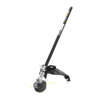
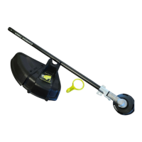
INSTALLING THE GRASS DEFLECTOR
EXTENSION
See Figure 3.
The grass deector extension must be attached before
switching from a bump head to the 2-in-1 head.
To install:
Align the tab of the grass deector extension with the slot
of the grass deector.
Align holes and insert one screw. Tighten slightly with a
Phillips screwdriver (not included).
Insert second screw and tighten both screws securely.
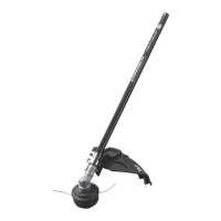
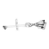
JOINING THE POWER HEAD TO THE
STRAIGHT SHAFT TRIMMER ATTACHMENT
See Figure 4.
WARNING:
Never attach or adjust any attachment while power head
is running. Failure to stop the motor may cause serious
personal injury.
The trimmer attachment connects to the power head by
means of a coupler device.
Stop the motor and disconnect from the power supply.
Loosen the knob on the coupler of the power head shaft.
Push in the button located on the trimmer attachment.
Align the button with the guide recess on the power head
coupler and slide the two shafts together. Rotate attach-
ment shaft until button locks into the positioning hole.
NOTE: If the button does not release completely in the
positioning hole, the shafts are not locked into place. Slightly
rotate from side to side until the button is locked into place.
Tighten the knob securely.
WARNING:
Be certain the knob is fully tightened before operating
equipment. Check it periodically for tightness during use
to avoid serious injury.
REMOVING THE ATTACHMENT FROM THE
POWER HEAD
For removing or changing the attachment:
Stop the motor and disconnect from the power supply.
Loosen the knob.
Push in the button and twist the shafts to remove and
separate ends.
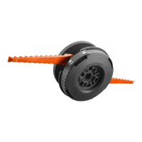
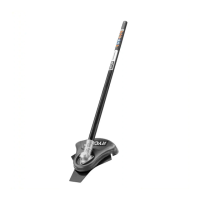
INSTALLING THE FIXED LINE/BLADE
HOUSING
See Figures 5 - 8.
NOTE: Do not attempt to install the xed line and the ail
blades in the xed line/blade housing at the same time.
Stop the motor and disconnect from the power supply.
Installing the flail blades:
Remove the bump feed trimmer head housing by rotat-
ing the lower housing counterclockwise so the arrow on
the upper housing aligns with the outside arrow on the
bump feed housing.
NOTE: The housing is spring loaded and will self eject
when unlocked. It is not necessary to remove the upper
string head housing from the drive shaft.
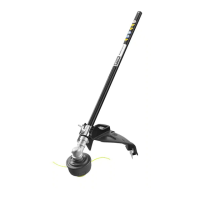
Place the ail blade over the post and press down until
it is fully seated.
Align the posts on the xed line/blade housing with the
arrows on the upper housing.
Push the housing together and rotate the lower housing
clockwise until the arrow aligns with the lock symbol on
the upper housing to secure the head in place.
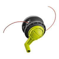
Installing the fixed line:
Fold a piece of pre-cut line in half so each half is equal
in length.
Insert the ends of the line through the eyelets in the post
and pull tight.
Repeat wth the other post.
The xed line/blade housing is now ready to use.