EasyManua.ls Logo

Ryobi P261 User Manual

Ryobi P261
20 pages
To Next Page IconTo Next Page
Page #1 background imageLoading...
Page #1 background image
OPERATOR’S MANUAL
MANUEL D’UTILISATION
MANUAL DEL OPERADOR
18 V IMPACT WRENCH
CLÉ À CHOCS 18 V
DESTORNILLADOR DE IMPACTO DE 18 V
P261
ACCEPTS ALL ONE+ BATTERY PACKS
COMPATIBLE AVEC TOUS LE PILES ONE+
ACEPTA TODOS LOS PAQUETES DE BATERÍAS ONE+
BATTERIES AND CHARGERS SOLD SEPARATELY
PILES ET CHARGEUR VENDUS SÉPARÉMENT
LAS BATERÍAS Y LOS CARGADORES SE VENDEN POR
SEPARADO
WARNING: To reduce the
risk of injury, the user must read and
understand the operator’s manual
before using this product.
ADVERTENCIA: Para reducir
el riesgo de lesiones, el usuario debe leer
y comprender el manual del operador
antes de usar este producto.
AVERTISSEMENT :
Pour
réduire les risques de blessures,
l’utilisateur doit lire et veiller à bien
comprendre le manuel d’utilisation avant
d’employer ce produit.
TABLE OF CONTENTS
General Power Tool
Safety Warnings ..............................2-3
Impact Wrench Safety Warnings ........ 3
Symbols ..............................................4
Assembly ............................................ 5
Operation .........................................5-6
Maintenance ....................................... 7
Figures (Illustrations) .......................8-9
Parts Ordering
and Service ........................Back page
TABLE DES MATIÈRES
Avertissements de sécurité générales
relatives aux outils électriques ........2-3
Avertissements de sécurité relatifs au
clé à chocs ......................................... 3
Symboles ............................................4
Assemblage ........................................5
Utilisation .........................................5-6
Entretien .............................................7
Figures (illustrations) ........................8-9
Commande de pièces
et dépannage ...................Page arrière
ÍNDICE DE CONTENIDO
Advertencias de seguridad para
herramientas eléctrica .....................2-3
Advertencias de seguridad
llave de impacto .................................3
Símbolos ............................................4
Armado ..............................................5
Funcionamiento ..............................5-6
Mantenimiento ...................................7
Figuras (illustraciones) ....................8-9
Pedidos de piezas
y servicio ....................... Pág. posterior
SAVE THIS MANUAL FOR
FUTURE REFERENCE
CONSERVER CE MANUEL
POUR FUTURE RÉFÉRENCE
GUARDE ESTE MANUAL
PARA FUTURAS CONSULTAS
Question and Answer IconNeed help?

Do you have a question about the Ryobi P261 and is the answer not in the manual?

Ryobi P261 Specifications

General IconGeneral
Voltage18V
Max Torque300 ft-lbs
Impact Rate0-3, 200 IPM
Battery CompatibilityRyobi 18V ONE+
Drive Size1/2 inch
Battery TypeLithium-Ion
Weight3.4 lbs (tool only)

Summary

General Power Tool Safety Warnings

Work Area Safety

Ensures a clean, well-lit work area, avoiding explosive atmospheres and keeping distractions away.

Electrical Safety

Covers proper plug matching, avoiding grounded surfaces, wet conditions, and cord safety.

Personal Safety

Emphasizes staying alert, using PPE, preventing unintentional starts, and proper dress.

Power Tool Use and Care

Focuses on using the correct tool, maintaining it, and safe storage practices.

Battery Tool Use and Care

Battery Charging and Compatibility

Use only specified chargers and battery packs; keep away from metal objects to prevent shorts.

Battery Handling and Leakage

Avoid contact with ejected battery liquid; flush with water if contact occurs.

Impact Wrench Safety Warnings

General Operation Safety

Covers safe handling, knowing the tool, and wearing appropriate personal protective equipment.

Battery Tool Operation Precautions

Addresses hazards related to battery tool operation, including fire, explosion, and proper charging.

Symbols

Signal Word Meanings

Explains the meaning of signal words like DANGER, WARNING, CAUTION, and NOTICE.

Product Symbol Explanations

Details the meaning of symbols used on the product for safe operation.

Assembly

Product Assembly Warnings

Warns against using incomplete or damaged products and modifying the tool.

Operation

General Operation Precautions

Advises on maintaining alertness, removing the battery pack when not in use, and wearing eye protection.

Applications

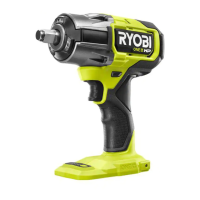
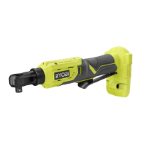
Lists the intended uses of the tool, primarily tightening and loosening nuts and bolts.

Variable Speed Switch Trigger

Explains how to operate the variable speed trigger for different speeds.

Direction of Rotation Selector

Details how to set the rotation selector for forward, reverse, or locked positions.

Installing/Removing Battery Pack

Provides instructions for correctly inserting and removing the battery pack.

Operation (Continued)

Tri-Beam LED Lights

Describes the function of the LED lights that illuminate when the switch trigger is depressed.

Installing and Removing Sockets

Instructions on using the correct size impact socket and how to install/remove it.

Speed Selector

Explains how to change the speed settings (LOW, MEDIUM, HIGH) for different applications.

Operating the Impact Wrench

Guidance on holding the tool, fastening time, and checking torque with a torque wrench.

Impact Time and Electric Brake

Discusses optimal impact duration and the function of the electric brake.

Maintenance

General Maintenance Precautions

Warns to use only identical replacement parts and avoid solvents when cleaning plastic parts.

Figures and Illustrations

Figure 1: Main Components

Diagram identifying the anvil, LED lights, switch trigger, and rotation selector.

Figure 2: Battery Pack Installation

Illustration showing how to install and remove the battery pack using latches.

Figure 3: Tri-Beam LED Lights

Diagram illustrating the placement and function of the Tri-Beam LED lights.

Figure 4: Socket Installation

Shows how to install an impact socket onto the anvil using the detent pin.

Figure 5: Speed Selector

Diagram illustrating the speed selector and its different speed settings (LOW, MEDIUM, HIGH).

Figures 6 & 7: Correct/Incorrect Operation

Illustrations demonstrating correct and incorrect ways to operate the impact wrench.

Service and Support

Requesting Service and Parts

Instructions for obtaining service, replacement parts, and customer support via website or phone.

Model and Serial Number

Guidance on locating the model and serial number from the product data plate.

Related product manuals