ASSEMBLY
11
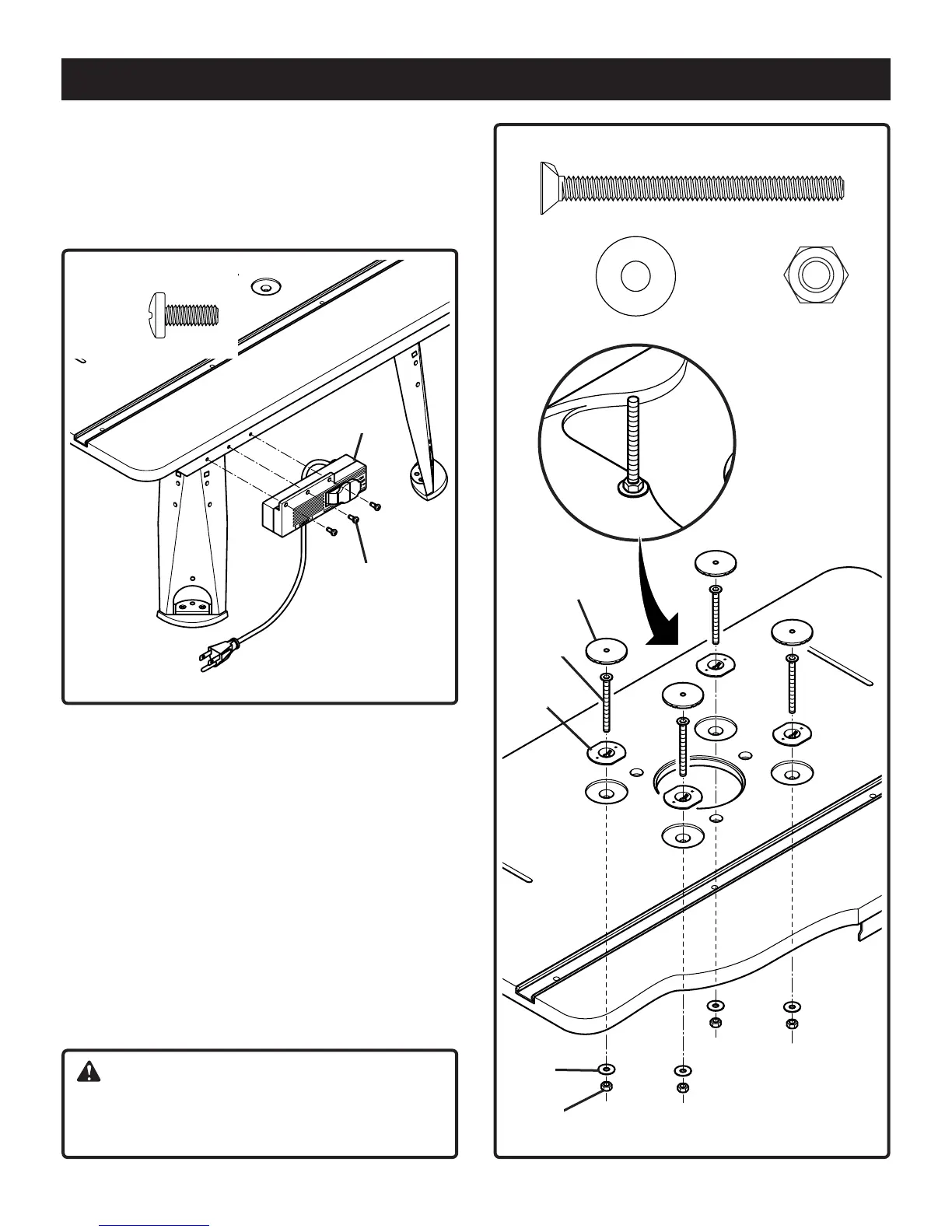
Fig. 3
TO ATTACH THE SWITCH BOX
See Figure 3
4. Place the router table on its legs.
5. Use a #2 Phillips screwdriver to attach switch box (G) to
the switch box bracket with 3 self tapping screws (AF).
To attach screws, washers and nuts for
mounting router
See Figure 4
6. Place the 4 flange nuts (U) in the 4 countersink holes of the
tabletop.
7. Insert the 4 countersink screws (AC) through holes in table
top. Tighten securely with the 4 hex nuts (AD) placing the
4 washer (AE) between the nuts (AD) and the tabletop.
Use an adjustable wrench or a combination wrench
(size 10 mm) to tighten the nuts (the detail in figure 4
shows the finished assembly).
8. Press the 4 caps (K) to cover the heads of the
countersink screws.
NOTE: Press the caps down until they are flush with table
top.
AF (3)
G
AF
AC (4)
AD (4)AE (4)
Fig. 4
AC
K
AE
U
AD
CAUTION:
If you choose not to use the universal router mounting
system, simply remove the associated hardware (AD,
AE, U, AC), but keep the caps (K) in place.
Bdal 6146.461 3Sprachen 04.06.2005 11:58 Uhr Seite 11