INSTALLATION—THE BOTTOM BAR
THE BOTTOM
BAR
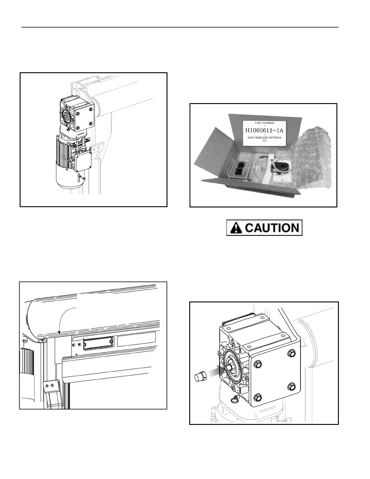
1. Check the brake release lever located on the motor/
brake assembly. The brake must be in the UP
engaged position. (See Figure 22.)
Figure 22
NOTE: When released, the motor brake will default to
the ENGAGED position.
2. Cut and remove the shipping bands holding the
fabric to the roll.
3.
Insert the plastic tabs on the bottom bar into the slot
of each side column. (See Figure 23.)
Figure 23
THE ENCODER MAGNET, ENCODER AND
WIRELESS ANTENNA
Locate the wireless antenna parts box (labeled part
number H1060612-1A) in the crate. The box holds the
encoder magnet, the wireless antenna, and the
encoder. The wireless antenna is pre-installed on its
mounting bracket, and the encoder is pre-installed on
its white mounting plate.
Figure 24
The wireless antenna and the encoder are
connected by a pre-installed wire. Make sure the
antenna is supported while the encoder is installed.
Excess tension can damage the wire.
Install the encoder magnet
1. Remove the two hex set screws from the magnet
and apply a mild thread lock to each.
Figure 25
2. Slide the magnet over the drum shaft. Re-install
and tighten the set screws. (See Figure 25.)
break
release
Plastic Tabs on Bottom Bar
Fit into Slot in Side Column
 Loading...