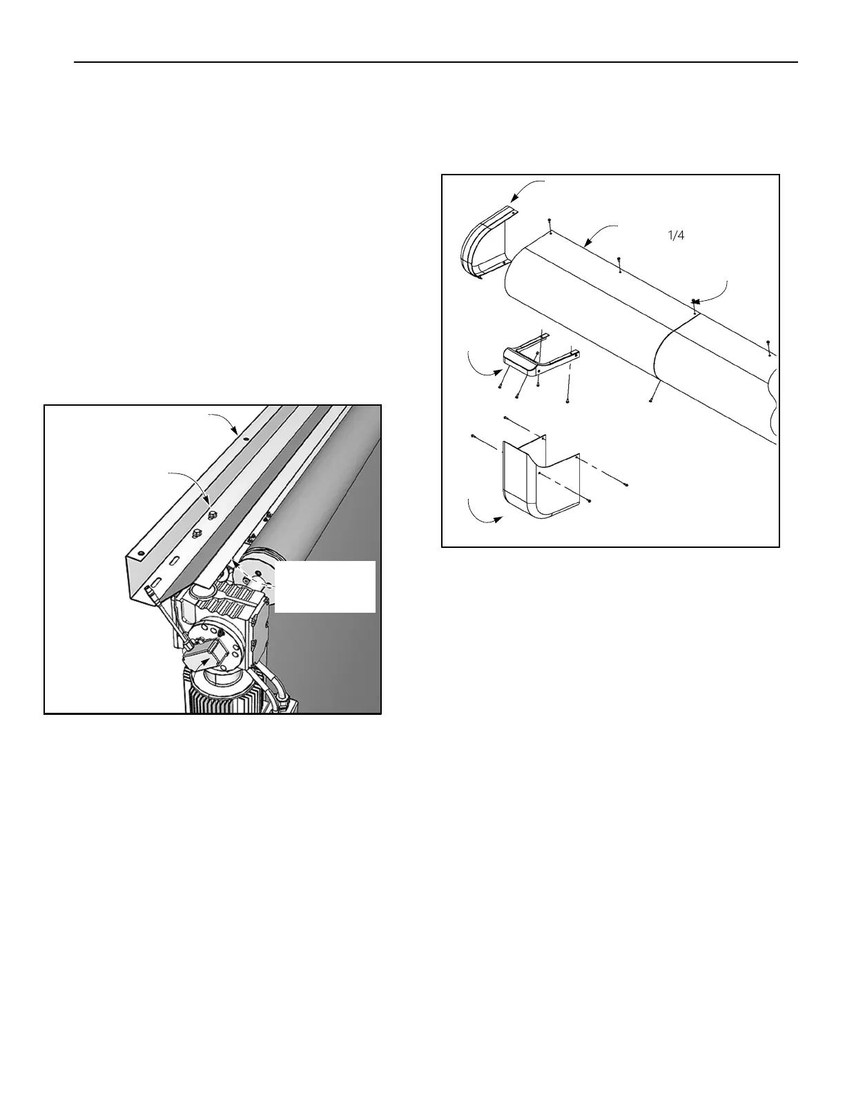
(Two Each Side
1/4-20 UNC x 3/4
Serrated-Flange
Hex Screw
Bracket
Head Screw
INSTALLATION—ABS HOOD (OPTIONAL)
ABS HOOD (OPTIONAL)
1. Attach the hood support assembly to the
top of the side
columns
using two
3/8-
16
x 1-in. serrated-flange hex screws
and nuts on each end. (See Figure 54.)
2. Attach the center hood cover section
(one-piece hood) or the end hood cover
sections (three- or four-piece hood) to the
head extrusion. (See Figure 52.)
Secure
cover
to
extrusion
and
end panels
using
#12 x 3/4
-in.
self-tapping sheet metal
screws.
INSTALLATION—ABS HOOD
(OPTIONAL)
A9800019
Figure 54
3. Assemble the motor cover, motor bracket, hood
cap, and hood using 1/4-20 UNC x 3/4 serrated-
flange hex screws. (See Figure 55.)
Figure 55
4. Install the center hood piece(s) and other hood
cap.
NOTE: Pay close attention to the reliefs in the hood
assembly.
The
middle hood sections
overlap each
piece for a smooth and clean assembly. The two
hood caps tuck under the middle hood sections,
followed by screws to tighten and finish off the
assembly.