2. TERMINAL DESCRIPTION
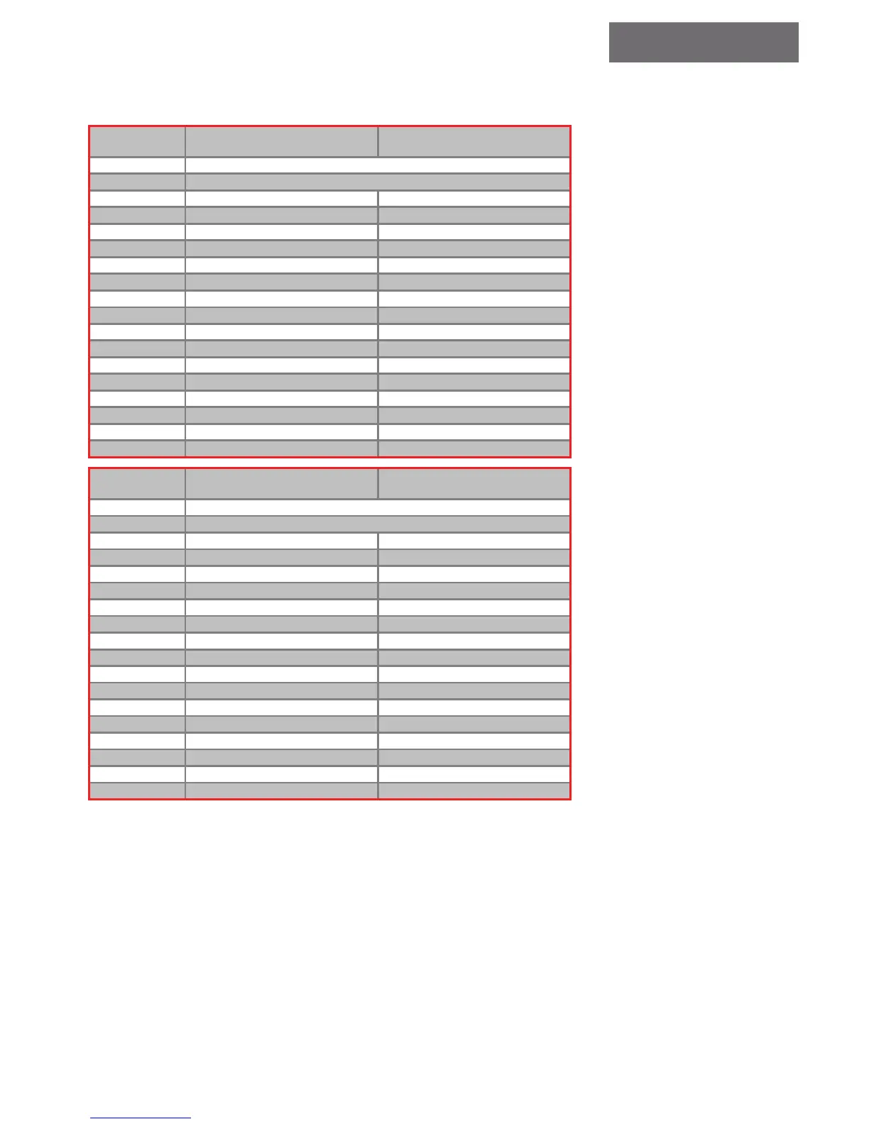
The table below shows how the calls are allocated on the extension board #2:
With 2
Extensions
Down Collecve
Full Collecve
P
+22
V
Biasing voltage from periphery supply – posive side
GND
Biasing voltage from periphery supply – negative side
EC
0 Car 16 Down 1
EC
1 Car 17 Down 2
EC
2 Car 18 Down 3
EC
3 Car 19 Down 4
EC
4 Car 20 Down 5
EC
5 Car 21 Down 6
EC
6 Car 22 Down 7
EC
7 Car 23 Down 8
EC
8 Down 16 Down 9
EC
9 Down 17 Down 10
EC
10 Down 18 Down 11
EC
11 Down 19 Down 12
EC
12 Down 20 Down 13
EC
13 Down 21 Down 14
EC
14 Down 22 Down 15
EC
15 Down 23 -
With 3
Extensions
Down Collecve
Full Collecve
P
+22
V
Biasing voltage from periphery supply – posive side
GND
Biasing voltage from periphery supply – negative side
EC
0 Car 16 Down 1
EC
1 Car 17 Down 2
EC
2 Car 18 Down 3
EC
3 Car 19 Down 4
EC
4 Car 20 Down 5
EC
5 Car 21 Down 6
EC
6 Car 22 Down 7
EC
7 Car 23 Down 8
EC
8 Car 24 Down 9
EC
9 Car 25 Down 10
EC
10 Car 26 Down 11
EC
11 Car 27 Down 12
EC
12 Car 28 Down 13
EC
13 Car 29 Down 14
EC
14 Car 30 Down 15
EC
15 Car 31 Down 16
Down calls starting at ground oor level and below are internally converted to up calls. The position of the ground oor is determined by setting the number of basements; refer to
section 5. For instance if there are no basements, then the ground oor is on the rst level and consequently Down 0 call will be internally interpreted as an Up 0 call.
Although this is not a call, it is listed with the calls for convenience.
 Loading...