MRL100 / 942 / 699Plus A1- Instruction Manual
Digital load / weight measuring system
S2Tech srl Via Imperia, 28 Milano – ITALY
Tel: +39 02 8910142 Fax: + 39 02 89124848
e-mail: info@s2tech.it
www.s2tech.it
Version : UK 2r7 dated 25/06/15
Page: 4/4
Notice: The information in this manual is subject to change without notice.S2Tech shall not be liable for technical or editorial errors or omissions contained herein, nor for incidental or consequential damages resulting from the furnishing, performance, or use of this material. This manual contains information protected by
copyright. No part of this manual may be photocopied, or reproduced in any form, or translated without prior written consent from S2Tech. Z:\Manuali\LM MRL100_942_699A1\Traduzioni Maggio 2015\LM MRL_942_699A1 V2r7 UK .docx
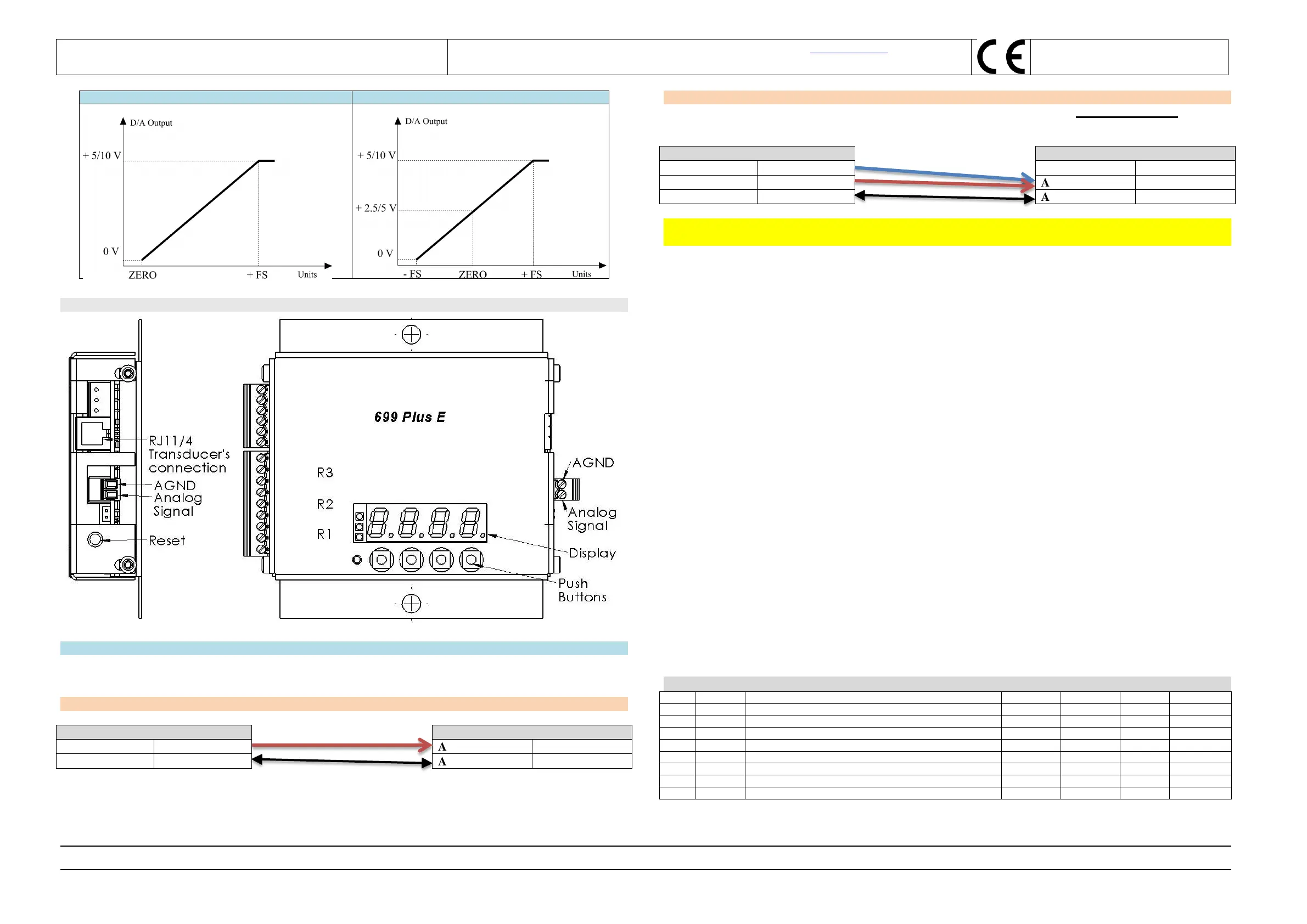
Note: 0 to 10V output signal is available for 699 Plus A1 electronics (code 00.03.010.0010).
J) Analog output connection scheme for code 00.03.010.0010:
Analog Signal A1 = from 0 to 10V
NOTE:
In order to obtain the best accuracy from the instrument’s analog output signal it is mandatory to connect 699Plus
analog output to the Inverter’s input, considering its input characteristics:
A) Inverter with floating input: 2 wire connection
B) Inverter with differential input: use 3 wires to connect the lift’s Inverter to 699Plus analog output, i.e.:
1. Connect JP11.1 and JP11.2 to 699Plus’s screw terminal analog output GND at the 699Plus's end.
2. Connect JP11.3 to Analog Output signal.
WARNING: POWER SUPPLY MINUS, provided to 699Plus instrument is NOT the AGND analog output
ground.
Document history
Updated analog output connections
Revision for MRL100 and 699PlusE images
Text revised – max load, inverter, DAC flow chart
Text revised on Inverter’s connection
 Loading...