EasyManua.ls Logo

Saab 1987 900 - Turbocharger and APC System

Saab 1987 900
96 pages
Print Icon
To Next Page IconTo Next Page
To Previous Page IconTo Previous Page
Loading...
46
Technical description
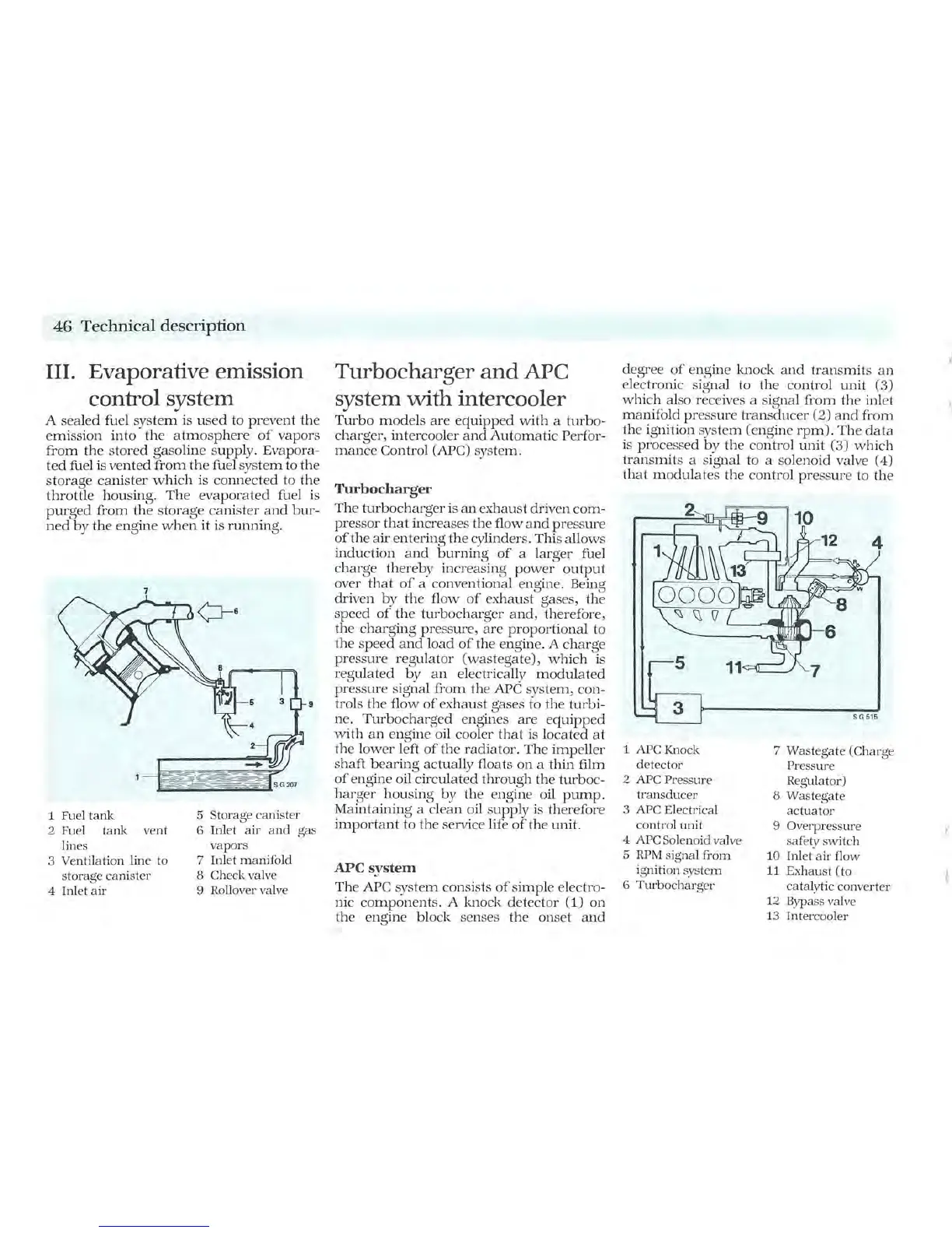
III. Evaporative
emission
control system
A
sea
l
ed
fuel
system
is
us
ed to
pr
event
the
emission
in
to
the
atmosphere
of
vapors
from
th
e
stored
gasoline
supply. Evapora-
ted
fuel is
vented
from
the
fuel
system
to
the
storage
canister
which
is
connected
to
the
throttle
housing.
The
evaporated
fu
el is
purged
from
the
storage
canister
a
nd
bur-
ned
by
the
engine
when
it
is
running.
7
1
Fue
l tank
2
Fue
l tank vent
lines
3 Ventilation line
to
storage canister
4 Inlet air
9
5 Storage canister
6 Inlet air a
nd
gas
vapors
7 Inlet manifold
8 Check
valv
e
9
Rollover
valve
Turbocharger
and
APC
system
with
intercooler
Turbo
models
are
equipp
ed
with
a
turbo-
charger
, intercooler
and
Automatic
Perfor-
mance
Control (APC) system.
Turbocharger
The
turbocharger
is
an
exhaust
dr
iven
com-
pressor
that
increases
the
flow a
nd
pressure
ofthe
air
ent
er
ing
the
cylinders. This
allows
induction
and
burning
of
a
larg
er
fuel
charge
ther
e
by
increasing
power
output
ov
er
that
of
a conventional engine. Being
driv
en
by
the
flow
of
exhaust
gas
es,
the
speed
of
th
e
turboch
a
rger
and,
th
erefore,
th
e
charging
pr
ess
ur
e,
are
proportional
to
the
speed
and
load
of
the
en
gine. A
charge
pressure
regulator
(wast
egate),
which
is
regulat
ed
by
an
electrically
modulat
ed
pressure
signal
from
the
APC sys
tem,
con
-
trols
the
flow
of
ex
haust
gases to
th
e
turbi-
ne.
Turbocharg
ed
engines
are
equipped
with
an
engine oil cooler
that
is loc
at
ed
at
the
lower
left
of
the
radiator.
The
impeller
shaft
b
ea
ring
actually
flo
ats
on
a
thin
film
of
engine oil
circulated
through
the
turboc-
harger
housing
by
the
engine oil
pump.
Maintaining
a cl
ea
n oil
supply
is therefore
important
to
the
service
lif
e
ofthe
unit.
APe
system
The
APC system consists
of
simple
electro-
nic
components.
A knock
det
ect
or
(1)
on
the
engine
block
senses
the
onset
an
d
degree
of
engine
knock
and
transmits
an
electronic signal to
the
control
unit
(3)
which
also receives a signal
from
the
inlet
manifold
pr
ess
ur
e
transducer
(2)
and
from
the
ignition
system
(engine
rpm).
The
data
IS processed
by
the
control
unit
(3)
which
transmits
a signal to a solenoid valve (4)
that
modulat
es
the
control
.
pr
ess
ur
e to
the
1 APCKnock
detector
2
APC
Pressure
transducer
3
APC
Electrical
control unit
4
APC
Solenoid
valve
5 RPM signal from
ignition system
6 Turbocharger
7 Wastegate (Charge
Pressure
Regulator)
8 Wast
eg
ate
actuator
9 Overpressure
sa
fety
switch
10
Inlet air flow
11 Exhaust (to
catalytic converter
12
Bypass
valve
13
Inter
co
oler
.t
"
"
,