Do you have a question about the Sabiana 4051180 and is the answer not in the manual?
Specifies intended use by expert or trained users in shops, industry, farms, or commercial settings.
States the unit is not for use by persons with reduced capabilities unless supervised.
Children should be supervised to ensure they do not play with the appliance.
Strongly advises users to read instructions carefully before operating the unit.
Provides a legend for the components shown in the electrical panel diagram.
Identifies the standard MB version and the version with an electric heater.
Provides a legend for the components shown in the electrical panel diagram.
Explains the function of each component labeled on the electronic board diagram.
Explains the function of each component labeled on the electronic board diagram.
Describes the CA contact for remote ON-OFF or Summer/Winter Change-Over.
Describes the CF contact for window open or presence sensor.
Describes the D0-D0 contact and its function based on DIP 8 position.
Details the CA contact operation for remote ON/OFF and Summer/Winter modes.
Explains the CF contact functionality for window open and presence detection.
Details the D0-D0 contact's behavior based on DIP 8 settings for machine or pump status.
Provides a table detailing DIP switch settings and their corresponding functions.
Provides a table detailing LED signals and their meanings.
Details DIP switch settings and their corresponding functions.
Details the LED signals and their meanings for different states.
Explains the standard operation of the fan and its control settings.
Details the Autofan function, including standard operation and control.
Explains how to manage multiple devices connected serially via a single remote control.
Details serial connection setup and the role of the end network jumper.
Describes managing multiple devices in a serial connection, including Master/Slave roles.
Explains serial connection procedures and the use of the end-of-line jumper.
Specifies the type of shielded cable required for serial connections.
Details the type of conductor required for serial communication lines.
Guidelines for safe and correct cable installation, routing, and connection practices.
Safety precautions regarding cable placement to avoid accidental contact and interference.
Procedure for verifying cable condition and placement after installation.
Best practices for cable installation, connection, and routing to ensure proper function.
Safety measures for cable placement, avoiding interference and hazards from proximity to electrical and other systems.
Procedure for verifying the condition and placement of installed cables.
Prohibits placing communication cables with power or lighting cables in conduits or containers.
Ensures adequate separation between communication cables and other electrical cables, maintaining distance from inductive loads.
Details connection symbols for serial linking and warns against reversing connections.
Specifies respecting connection symbols for serial connection of devices.
Details the T2 probe for Change-Over function, including its installation and use.
Explains the operating logic of the unit when using the T2 probe for temperature sensing.
Provides technical specifications for the T2 probe, including type and resistance.
Instructions for connecting the T2 probe wires to the board terminals.
Describes the T2 probe for Change Over functionality and its installation requirements.
Explains the functional logic of the unit when using the T2 probe.
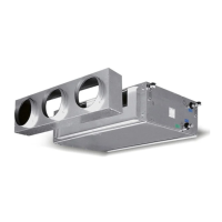
Illustrates the initial steps for installing the ceiling unit, showing placement and securing.
Continues the illustration of ceiling unit installation, showing further assembly steps.
Illustrates the step for securing the unit during ceiling installation.
Shows final steps of ceiling unit installation, including flap adjustment and panel closure.
Instruction to insert batteries before operating the remote control and specifies the required AAA 1.5 Volt type.
Warning regarding proper disposal of batteries, advising use of designated containers.
Instruction to insert supplied batteries and specifies the required AAA 1.5 volt type.
Warning against abandoning batteries in the environment and advises using special waste containers.
Identifies the remote control as infrared-based.
Explains that the remote control must be aimed at the receiver on the cassette unit to send commands.
States the remote control operates via infrared signals.
Explains the need to point the remote control at the cassette unit's receiver for command transmission.
Instructs to press 'ON/SEND' to send operating parameter changes to the fan coil unit.
Explains that pressing the 'OFF' button is sufficient to switch off the appliance.
Details sending instructions to modify operating parameters via the 'ON/SEND' button.
Explains how to stop the appliance by pressing the 'OFF' button.
Guides on how to set the desired start time for the appliance's operation.
Explains how to send the configured operating mode information to the appliance.
Details selecting the operating mode and setting the clock time and day.
Guides on selecting operating modes and modifying the desired temperature set point.
Explains how to send the set point information to the appliance.
Details how to adjust the desired temperature set point and send the information.
Guides on selecting fan operating speed: low, medium, high, or automatic.
Explains how to send the selected fan mode information to the appliance.
Details selecting the fan operating mode (low, medium, high, automatic) and sending the command.
Guides on selecting operating modes: Fan, Heating, Cooling, or Automatic.
Explains how to send the selected operating mode information to the appliance.
Details selecting operating modes (Ventilation, Heating, Cooling, Automatic) and sending the command.
Guides on how to activate or deactivate the timer function using the remote control.
Explains how to program the timer for start times.
Details setting the timer's start time, including selecting hours and minutes.
Guides on setting the timer's stop time, including selecting hours and minutes.
Explains how to send the programmed timer settings to the appliance.
Explains the functionality when the timer is deactivated.
Details the timer's operation when activated, including cycle repetition.
Explains how the vertical flaps manage air flow based on the selected operating mode (Cooling/Heating).
Details vertical flap position for cooling mode (40°).
Details vertical flap position for heating mode (60°).
Warns against manually adjusting the vertical flap's position.
Explains how to set a specific airflow direction or activate the SWING mode.
Describes vertical flap control and its variation based on operating modes.
Caution against manually adjusting the vertical flap position.
Guides on activating, deactivating, and operating the SWING function, including display indications.
Instructions for stopping the flap and safety warnings regarding manual adjustment and remote control use.
Guides on activating, deactivating, and operating the SWING function, including display indications.
Instructions for stopping the flap and safety warnings regarding manual adjustment and remote control use.
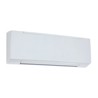
Describes the T-MB controller for wall installation, its connectivity, and network capabilities.
Lists the primary functions controllable via the T-MB unit.
Provides a list and explanation of the symbols displayed on the T-MB control panel.
Crucial instruction to read the manual carefully before installation and use.
Details the T-MB wall-mounted controller and its compatibility with cassette or fan coil units.
Lists the main functions controllable by the T-MB unit, including power, fan speed, temperature, and mode.
Explains the meaning of various signal indicators on the T-MB control panel.
Strong recommendation to carefully read the manual before installation and use of the controller.
Instructions for separating the front part of the controller from the rear plate.
Steps for positioning the rear plate, marking, drilling, and inserting wall plugs.
Instruction to make electrical connections according to the wiring diagram on the next page.
Warning regarding removal of the insulated protection device for electrical connections.
Procedure for reassembling the controller's front part after connections.
Instructions for removing the controller's front cover by pressing the locking tongue.
Steps for wall mounting the rear panel, marking holes, and drilling.
Guidance to perform electrical connections as per the wiring diagram on the subsequent page.
Warning about removing the terminal's insulation protection for T-MB controller wiring.
Procedure for reassembling the controller's front part after making connections.
Details wiring the control panel to the unit's power board, respecting numbering.
Specifies the use of 3 conductors with a 0.5 mm² cross-section for connections.
Notes the maximum allowed connection cable length of 20 meters.
Emphasizes the importance of following the correct wiring sequence.
Explains connecting the control panel to the power board, ensuring correct numbering correspondence.
Specifies using 3 conductors with 0.5 mm² cross-section for connections.
Notes the connection cable length must not exceed 20 meters.
Stresses the importance of observing the correct connection sequence.
Explains the DIP block's purpose for modifying controller functions as per the table.
Details the use of DIP 2 to enable either the T-MB sensor or the T1 probe.
Provides descriptions of functions associated with DIP switch settings.
Explains how DIP 2 enables room air temperature probes (T-MB or T1) and their activation.
Explains how to turn the thermostat on and off using the ON/OFF button.
Guides on adjusting the desired temperature set point using the '+' or '-' buttons.
Details how to select operating modes (Cooling, Heating, Automatic, Fan) using the 'M' button and '+' or '-' buttons.
Explains how to select fan speed (low, medium, high, automatic) using the 'FAN' button.
Describes how to turn the control unit on and off using the ON/OFF button.
Explains how to set the desired temperature using the '+' or '-' buttons.
Details how to select operating modes (Cooling, Heating, Automatic, Fan) using the 'M' button.
Explains how to select fan speed (low, medium, high, automatic) using the FAN button.
Guides on pressing the 'M' button to make the mode symbol flash.
Instructions to select the watch symbol using '+' or '-' buttons and confirm with 'M'.
Guides on positioning to CLOC mode and confirming with the 'M' button.
Explains how to set the current time using '+' or '-' buttons and confirming with 'M'.
Guides on selecting the day of the week and confirming with the 'M' button.
Instructions to press the 'M' button for 3 seconds to exit the program.
Details pressing the 'M' key to make the mode symbol flash and selecting the clock symbol.
Explains how to position to CLOC mode and confirm using the 'M' button.
Details setting the current time and day using '+' or '-' buttons and confirming with 'M'.
Instructions to press the 'M' button for 3 seconds to exit the program.
Guides on how to activate or deactivate the timer function using the 'M' button.
Informs that the timer defaults to OFF and guides on selecting TIMER OFF or ON.
Instructs to press the 'M' button for over 2 seconds to return to the operation mode.
Guides on activating or deactivating the timer function.
Details pressing the 'M' key to make the mode symbol flash and selecting the clock symbol.
Explains how to access the timer activation/deactivation menu.
Informs that the timer defaults to OFF and guides on selecting TIMER OFF or ON.
Instructs to press the 'M' button for over 2 seconds to return to the operation mode.
Guides on setting up the timer, including selecting modes, symbols, and confirming settings.
Explains how to program the timer for start and stop times for up to 7 days.
Instructs to press 'M' to confirm and return to the main menu or operation mode.
Guides on setting up the timer, including selecting modes, symbols, and confirming settings.
Explains how to program the timer for start and stop times for up to 7 days.
Instructs to press 'M' to confirm and return to the main menu or operation mode.
Explains how the vertical flaps manage air flow based on the selected operating mode (Cooling/Heating).
Details vertical flap position for cooling mode (40°).
Details vertical flap position for heating mode (60°).
Warns against manually adjusting the vertical flap's position.
Explains how to set a specific airflow direction or activate the SWING mode.
Describes vertical flap control and its variation based on operating modes.
Caution against manually adjusting the vertical flap position.
Guides on activating, deactivating, and operating the SWING function, including display indications.
Instructions for stopping the flap and safety warnings regarding manual adjustment and remote control use.
Guides on activating, deactivating, and operating the SWING function, including display indications.
Instructions for stopping the flap and safety warnings regarding manual adjustment and remote control use.
Explains the service menu's purpose: verifying parameters like probe values, contact status, and alarms.
Explains how to select parameters for verification and view their values.
Provides instructions to exit the service menu.
Details the display of various parameters including probe values, contact status, alarms, and voltage.
Guides on accessing, navigating, and verifying service menu parameters.
Details the display of various parameters such as probe values, contact status, alarms, and voltage.
Explains that this menu allows modification of thermostat, motor, version, and other parameters like pump cycle and RESET.
Explains how to select parameters for modification using '+' or '-' buttons and confirm with 'M'.
Guides on returning to parameter selection or exiting the menu.
Organizes parameters into categories for thermostat, probes, cycles, timers, and other functions.
Guides on accessing, navigating, modifying, and exiting the factory settings menu.
Organizes parameters into categories for thermostat, probes, cycles, timers, and other functions.
Explains the menu's purpose: modifying thermostat, motor, version, and other parameters like pump cycle and RESET.
Explains how to select parameters for modification using '+' or '-' buttons and confirm with 'M'.
Guides on returning to parameter selection or exiting the menu.
Organizes parameters into categories for thermostat, probes, cycles, timers, and other functions.
Guides on accessing, navigating, modifying, and exiting the factory settings menu.
Organizes parameters into categories for thermostat, probes, cycles, timers, and other functions.