EasyManua.ls Logo

Sabiana MB BOARD User Manual

Sabiana MB BOARD
41 pages
To Next Page IconTo Next Page
Page #1 background imageLoading...
Page #1 background image
B 11/12
E 05/13
Cod. 4050532EST
MANUALE D’USO SCHEDA MB
PER VENTILCONVETTORI CASSETTE
MB BOARD
FOR CASSETTE FAN COILS, USER MANUAL
NOTICE D’UTILISATION DE LA CARTE MB
POUR VENTILO-CONVECTEURS CASSETTE
DESkA MB PRO KAZETOVÝ FANCOIL
NÁVOD NA INSTALACI A ÚDRŽBU
MANUAL DE USO
DE LA TARJETA MB PARA
LOS VENTILADORES CONVECTORES
CASSETTE
HANDLEIDING MB kAART
VENTILATORS-CONVECTORS
CASSETTE

Table of Contents

Question and Answer IconNeed help?

Do you have a question about the Sabiana MB BOARD and is the answer not in the manual?

Sabiana MB BOARD Specifications

General IconGeneral
BrandSabiana
ModelMB BOARD
CategoryRemote Control
LanguageEnglish

Summary

Electronic Board and Component Identification

DIP Switch Configuration

DIP Switch Settings (DIP 1-10) and Functions

Details the function of each DIP switch for configuring the unit's operation modes and features.

Default Settings and Autofan Operation

Master-Slave Network Operation

Connecting Multiple Units in Master-Slave Configuration

Guides on connecting multiple fan coils in a serial network with a master unit.

RS485 Network Connection and Installation Guidance

RS485 Serial Connection Instructions and Cable Requirements

Provides critical instructions for connecting units via RS485, including cable type and network length.

Network Earthing and Wiring Connections

Electrical Connection Diagrams (Asynchronous Motor)

Wiring Diagram for 2-Pipe Systems (Asynchronous Motor)

Illustrates electrical connections for 2-pipe systems with asynchronous motors.

Wiring Diagram for 4-Pipe Systems (Asynchronous Motor)

Illustrates electrical connections for 4-pipe systems with asynchronous motors.

Electrical Connection Diagrams (ECM Motor)

Wiring Diagram for 2-Pipe Systems (ECM Motor)

Shows electrical connections for 2-pipe systems with ECM motors.

Wiring Diagram for 4-Pipe Systems (ECM Motor)

Illustrates electrical connections for 4-pipe systems with ECM motors.

Logical Operation with Electrical Heater

L1: Resistance as Exclusive Heating Element

Manages resistance coil as the sole heating source, equivalent to a 4-pipe system.

L2: Resistance as Integration Element (2-pipe system)

Integrates resistance coil into 2-pipe system heating, controlled in two stages.

Setting Desired Temperature

Fan Mode Selection

Operating Modes Selection

Timer Programming - Start Time

Timer Programming - Stop Time and Activation

T-MB Wall-Mounted Controller Features

T-MB Controller Features and Capabilities Overview

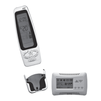
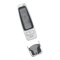
Lists the functionalities of the T-MB controller, including ON/OFF, fan speed, and temperature settings.

Controller Installation and Wiring

Electrical Wiring and Sequence Compliance

DIP Switch Functions and Probe Selection

Detailed DIP Switch Functions and Settings

Explains how DIP switches modify controller functions, including T-MB versions and probe selection.

Programming Timer Schedules (Start/Stop Times)

Factory Service Menu and Parameter Access

Accessing the Factory Service Menu

Details how to enter the service menu by pressing specific buttons.

Detailed Factory Parameter Settings

Thermostat Parameters (Offset, Dead Zone, Hysteresis)

Allows modification of thermostat parameters like offset, dead zone, and hysteresis.

T2, T3 Probe, and Stratification Cycle Parameters

Covers parameters for T2 Change-Over, T3 minimum temperature probes, and stratification cycle.

Related product manuals