Do you have a question about the Sabiana WM-UH-ECM and is the answer not in the manual?
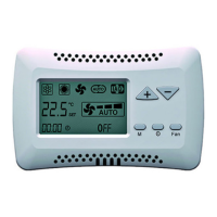
Overview of the WM-UH-ECM control panel, its design, materials, and installation suitability.
Identifies and describes the main components of the control panel, including boards, display, and terminals.
Details the primary functions and capabilities of the control panel for managing unit heaters.
Lists the physical and electrical specifications of the WM-UH-ECM control panel.
Visual representation of the control panel's physical dimensions through diagrams.
Illustrates the steps for physically mounting the control panel on a wall.
Close-up view of mounting screws and wall attachment for the control panel.
Shows how to access and connect wires to the terminal board.
Diagram showing the arrangement of electronic components and connectors on the main board.
Explains the function of each terminal, jumper, and connector on the electronic board.
Table detailing the function of each DIP switch position for system configuration.
Provides critical notes regarding unit heater operation modes and fan speed limitations.
Explains the use of the CA contact for remote ON/OFF or summer/winter mode selection.
Details the CF contact's role in activating antifreeze or night mode.
Describes the DO-DO contact's use for machine status or pump/boiler/chiller consent.
Table mapping LED status to operational states and errors.
Illustrates the wiring for connecting multiple units via a 0-10V signal.
Guidelines for connecting units using the Mod-Bus RS485 protocol.
Best practices for installing RS485 cables, including tightening and routing.
Details how to connect D-, D+, and shielding for RS485 network termination.
How to link multiple WM-UH-ECM controls for simultaneous operation.
Explains how to assign unique addresses to each unit using DIP switches (D1, D2).
Introduces the integrated T-MB controller and its basic functions.
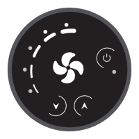
Identifies and explains the icons and symbols displayed on the T-MB controller.
Instructions for turning the unit on/off and adjusting the target temperature.
How to choose between cooling, heating, or ventilation modes using the control.
Guide to manually adjusting the fan speed to low, medium, or high.
How to switch the fan speed control between manual and automatic modes.
Step-by-step guide to set the current time and day of the week.
How to enable or disable the timer function on the control panel.
Detailed steps for setting activation and deactivation times for the timer.
How to enter the service menu by pressing specific buttons.
Explains how to view probe values, contact status, and alarms.
Guide for accessing and changing thermostat, motor, and other factory parameters.
Lists and describes various adjustable parameters for thermostats and pump timers.
Details the kit for the remote NTC air probe.
Step-by-step instructions for connecting the remote NTC probe to the control board.
Provides a multi-language key to identify components and wire colors used in the manual.
Wiring diagram for units of size 1 to 6, showing connections for power and components.
Illustrates wiring for Siemens and Watts actuators.
Wiring diagram for Janus-ECM/UC-ECM units of size 9.
Wiring examples for Siemens and Watts actuators used with Janus-ECM/UC-ECM.
| Type | Wall-mounted control panel |
|---|---|
| Compatibility | Sabiana fan coil units |
| Functions | fan speed control, heating/cooling mode selection |
| Display | LCD |
| Power Supply | 24V AC/DC |
| Operating Temperature | 0 to +50 °C |
| Dimensions (H x W x D) | 25 mm |