The Integra series is a line of microwave radio products manufactured by SAF Tehnika, JSC, designed for wireless data transmission. This manual covers the Integra, Integra-S, Integra-G, and Integra-GS models, with firmware version 3.20.19 and software version 2.37.
Function Description
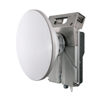
The Integra series FODUs (Full Outdoor Units) are designed for point-to-point microwave links, providing high-capacity data transmission. They feature Adaptive Coding and Modulation (ACM) and Automatic Transmit Power Control (ATPC) to optimize link performance and reliability under varying atmospheric conditions. The Integra-G models, specifically, incorporate a built-in Gigabit Ethernet Network Processor with three LAN ports: LAN1 (1Gbps PoE-in), LAN2 (SFP), and LAN3 (SFP). The Integra-S/Integra-GS models offer similar functionality with remote mount options for different frequency bands.
The devices support various aggregation and protection schemes, including 2+0 aggregation (link bonding) and 1+1 Hot Standby (HSB) protection, to enhance link capacity and redundancy. Traffic is split per-frame over two links in 2+0 aggregation, while 1+1 HSB uses one link at a time, with the second link's transmitters automatically muted. Header compression is also available to optimize bandwidth utilization by compressing excess protocol headers.
For networking, the Integra series supports VLANs (Virtual Local Area Networks) with port-based configuration, allowing up to 4094 different VLAN IDs. VLANs can be configured as tagged or untagged members on each LAN port, and default VLAN IDs and priorities can be set. Rate limiting can be applied to Ethernet switch ports, configuring ingress and egress rates. The devices also include a MAC address table for managing dynamic and static MAC address entries and support Spanning Tree Protocol (RSTP) for loop prevention and path redundancy. Synchronous Ethernet (SyncE) is supported to allow the Ethernet switch clock to be synchronized to an external source, ensuring stable timing for sensitive applications. Quality of Service (QoS) features include CoSQ (Class of Service Queue) scheduling, 802.1p mapping, DiffServ mapping, and MPLS EXP mapping, enabling prioritization of different types of traffic.
Important Technical Specifications
PoE Injector (P/N I0ATPI24/I0ATP144):
- Input Voltage: 20-65VDC
- Output Voltage: Stabilized to 54VDC
- Data Rate: Up to 1000 Mb/s
- Max Current: 1.2A (22-36V DC), 1.6A (36-60V DC)
- Power Clamping Voltage: +/- 70V
- Max Data Cable Length: 100m
- Operating Temperature: -10°C to +50°C
- Dimensions (W/H/D): 82mm/41mm/154mm
- Weight: 0.4kg
- Enclosure: Steel
Radio Specifications (example for Integra-18):
- Tx Frequency Range: 18182.75 - 18688.25 MHz
- Rx Frequency Range: 19192.75 - 19698.25 MHz
- Minimum Bandwidth: 1.75 MHz (inquire SAF representative for more information)
- AES Encryption: 256-bit key (64 hexadecimal characters)
- Modulation: Up to 512QAM FEC (or WeakFEC for highest modulation)
- Tx Power: Adjustable, range depends on radio model and modulation.
- Rx Level Range for ATPC: -75 to -40 dBm (at least 3dB difference between min/max).
Antenna and Polarization:
- Default polarization for licensed frequency band radios is vertical.
- Integra series 17/24GHz FODUs are shipped with opposite polarizations pre-installed for low and high side units.
- Integra-S/Integra-GS 6-13GHz FODUs feature a twisted polarization flange, with signal polarization determined by the antenna/OMT interface. The radio always remains in a vertical position.
Usage Features
Installation:
- Mounting: Integra/Integra-G FODUs can be installed with an antenna on a pole using a mounting bracket. Integra-S/Integra-GS FODUs attach directly to the antenna adapter flange.
- Polarization Change: For Integra/Integra-G, polarization is changed by removing the FODU from the mounting bracket, rotating it 90 degrees, and reattaching. For Integra-S/Integra-GS 6-13GHz, only the antenna interface is rotated.
- Antenna Alignment: Azimuth and elevation angles are adjusted using eye screws and hex flange nuts on the mounting bracket. Each notch on the azimuth angle indicator corresponds to one degree.
- Fiber Optic Interface: A fiber conduit kit is used to connect the FO interface to SFP ports (LAN2 or LAN3).
- Remote Mount Kit: Integra-GS models support remote mount kit assembly for different frequency bands.
- Indoor Setup: A test kit (adapter flange, waveguide-to-coaxial adapter, attenuators, coaxial cable, or test tube for 17/24 GHz) is available for indoor interconnection and initial setup.
Web GUI (Graphical User Interface):
- Access: Accessed via a web browser (Chrome, Firefox, IE8+) by entering the FODU's IP address (default: 192.168.205.10 for low side, 192.168.205.11 for high side). Default credentials: admin/changeme.
- Main Page: Provides an overview of system parameters, including license status, radio side, Tx mute, Tx power, ATPC, duplex shift, frequencies, Rx level, bandwidth, modem profile, ACM engine status, MSE, FEC load, current Rx/Tx modulation, Ethernet capacity, and port status.
- Configuration: Allows modification of radio parameters (Tx power, Tx frequency, Tx mute, RSSI Audio/LED, ATPC settings, bandwidth profile, modem profile, LAN port state) and networking parameters (VLANs, rate limits, MAC address table, Spanning Tree, SyncE, QoS).
- Aggregation/Protection: Configures 2+0 aggregation or 1+1 HSB protection, defining roles (Master/Slave), instance IDs, and Ethernet traffic ports.
- Header Compression: Enables or disables header compression and selects compression profiles.
- AES Encryption: Activates and configures AES 256-bit encryption by uploading a license key and setting a 64-hexadecimal character key.
- System Management: Includes firmware upgrade, IP configuration, SNMP settings, configuration file management, user management, system services, syslog, diagnostic tools (loopback), and license management.
Command Line Interface (CLI):
- Provides commands for status checks and configuration of radio, modem, network, and system parameters, offering an alternative to the Web GUI.
Maintenance Features
Monitoring and Diagnostics:
- Alarm Status: Displays active alarms and their types.
- Alarm Event Log: Stores up to 5000 alarm entries, showing date, time, source, status (SET/RESET), and event description. The log can be filtered by source node and downloaded as a text file.
- Sensor Configuration: Allows grouping sensors and defining data destinations (event, perf, snmp, syslog) for monitoring.
- Alarm Threshold Configuration: Provides predefined and dynamically changing alarm thresholds for various parameters (PSU current/voltage/power, modem/radio temperature, carrier offset, FEC load, MSE, Rx level, ATPC Tx power correction, internal voltages, system memory/CPU usage, uptime). Thresholds can be manually modified.
- Performance Graph: Visualizes two chosen parameters (e.g., Rx level and MSE) over a selected time period (1, 15, or 60 minutes granularity).
- Performance Log: Allows viewing and downloading performance logs in XML format, showing minimum, maximum, and average values for selected parameters over specified time intervals.
- Ethernet Switch Statistics: Provides detailed statistics for each LAN port, including ingress/egress bytes, packets, unicast/multicast/broadcast packets, FCS errors, and various error counts.
- QoS Statistics: Displays QoS-related statistics for each port.
- Rx Spectrum: Shows the received signal spectrum.
- Constellation Diagram: Visualizes the modem's constellation diagram for signal quality assessment.
- Equalizer Graph: Displays equalizer performance.
- Modem Performance: Provides modem-specific performance data.
- Troubleshooting File: Allows downloading a troubleshooting file for support.
System Management:
- Firmware Upgrade: Facilitates uploading and upgrading firmware versions via the Web GUI or CLI.
- Configuration File: Allows saving and loading configuration files.
- License Management: Manages time-limited and unlimited licenses, including uploading and activating new license keys.
- User Management: Configures user accounts and access rights.
- System Services: Manages various system services.
- Syslog: Configures syslog settings for logging events.
- Loopback Configuration: Enables loopback testing for diagnostic purposes.
- Factory Reset: Resets radio settings to factory defaults, disabling Tx power and setting frequencies to default values.
Physical Maintenance:
- FODU: FODU does not contain serviceable parts. Warranty is void if the FODU is hermetically unsealed.
- Grounding: Proper grounding connection is essential for safety and performance.
- Drain Hole: When polarization is changed, ensure the drain hole cap is removed and inserted into the new drain hole to allow water drainage.
- Sunlight Protection: It is recommended to protect the installed radio from direct sunlight.
- RSSI LED: Provides visual indication of current Rx level and polarization alignment accuracy.