EasyManua.ls Logo

SAF Tire Pilot Plus - Troubleshoot Manual

SAF Tire Pilot Plus
4 pages
Print Icon
To Next Page IconTo Next Page
Loading...
XL-AA20023TS-en-US Rev A · 2019-04-04 · Amendments and Errors Reserved · © SAF-HOLLAND, Inc., SAF-HOLLAND, HOLLAND, SAF,
and logos are trademarks of SAF-HOLLAND S.A., SAF-HOLLAND GmbH, and SAF-HOLLAND, Inc.
Figure 2
SAF
®
Tire Pilot Plus
Pressure Management System March, 2019
Troubleshooting Guide
All Trailer Axles
Refer to the link here for a troubleshooting video.
https://vimeo.com/user82815417/review/262250351/e88ebf4fc5
Symptom:
Warning Light on
Problem:
System air pressure low between 10-20 PSI of regulator
setting.
Solution:
Check for system air leaks. Connect air supply and pressurize
air tank. Open Tire Pilot Plus air system valve on the regulator
box as illustrated in Figure 1. If the leak is audible, use soapy
water to pin point the leak. If the leak is not audible, disconnect
all tire hoses from the hubcaps as illustrated in Figure 2.
If after removing tire hoses light stays on, the leak is present
between the hubcap and the air tank. Check the axle vents,
hubcap fittings, air tank fittings, pressure protection valve, and
airline external to the axle for leaking air with soapy water. If
after removing the tire hoses the light shuts off, the leak is at
the tire or tire hose. Reconnect each tire hose until the light
comes back on to pin point the leak. Once the leaking wheel
is found, use soapy water to discover the source including
wheel hoses, valve stems, rim to tire, and tire tread. Repair or
Replace leaking component as necessary or move to the next
appropriate troubleshooting section below.
Figure 1
VALVE (FOR SYSTEM
PRESSURE CHECK)
AIR SYSTEM VALVE
(SHOWN OPEN)
Question and Answer IconNeed help?

Do you have a question about the SAF Tire Pilot Plus and is the answer not in the manual?

Summary

Troubleshooting System Air Leaks

Warning Light and Low System Pressure

System air pressure low between 10-20 PSI of regulator setting, triggering a warning light.

Axle and Hubcap Leak Diagnosis

Air Leak from Axle Vent

Air leak detected inside the axle or within the hubcap assembly.

Spindle Plug Fitting Leaks

Leaks originating from spindle plug fittings due to loose nuts or damaged tubing.

Air System Pressure and Flow Issues

Low Brake Air Tank Pressure

Brake air tank pressure is low due to valve issues or connection leaks.

Incorrect Tire;System Pressure Readings

System pressure readings are low/high due to regulator setting or leaks.

Specific Component and System Checks

No Air Flow Through Regulator

Issues with air system valve being closed or pressure protection valve backwards.

Hose Leaks at Valve Stem or Hubcap

Hose fittings are loose or have been over-tightened, causing leaks.

Water in Hubcap

Potential causes include loose oil plug, damaged gasket, or axle vent issues.

Tire Pressure Low or Flat

System has an air leak, possibly in the tire hose or the tire itself.

Warning Light Not Activating

Warning light fails to illuminate when system pressure is low.

Overview

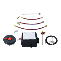
The provided document describes the SAF® Tire Pilot Plus™ Pressure Management System, a device designed for troubleshooting and maintaining optimal tire pressure in trailer axles. This system aims to prevent issues such as low tire pressure, which can trigger a warning light, and addresses various air leak scenarios.

Function Description:

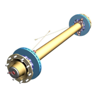
The SAF® Tire Pilot Plus™ system is primarily a pressure management system for trailer axles. Its core function is to monitor and maintain tire pressure within a specified range, typically between 10-20 PSI of a set regulator pressure. When the system detects low air pressure, it activates a warning light to alert the operator. The system includes an air system valve, a regulator, and various fittings and hoses that connect to the hubcaps and tires. It uses a pressure protection valve to ensure proper air flow and prevent over-pressurization. The system is designed to automatically adjust and maintain tire pressure, contributing to improved safety, fuel efficiency, and tire longevity.

Important Technical Specifications:

While specific numerical technical specifications like pressure ranges for individual components are not explicitly listed in a dedicated section, the document provides operational parameters and settings:

  • Regulator Setting: The system operates based on a regulator setting, with examples ranging from 80 psi to 120 psi.
  • Pressure Switch Settings: The document includes a table detailing the relationship between the regulator setting, valve pressure switch pressure, and control light pressure switch pressure. For instance, a regulator setting of 80 psi corresponds to a valve pressure switch pressure of 70 psi and a control light pressure switch pressure of 70 psi. Similarly, a 120 psi regulator setting corresponds to 90 psi for both pressure switches. This indicates that the pressure switches are calibrated to trigger at a certain threshold below the desired regulator setting.
  • Fitting Torque: For compression-type fittings, a tightening torque of 6-10 in-lbs (or hand tight plus two wrench flats) is specified.
  • Cap Size: A 1/8" NPT cap is used for the rotating shaft end.

Usage Features:

The system is designed for ease of use in monitoring and maintaining tire pressure.

  • Warning Light: A primary usage feature is the warning light, which illuminates when system air pressure is low (10-20 PSI below regulator setting), providing an immediate visual alert to the operator.
  • Air System Valve: The system includes an air system valve (shown open in Figure 1) that allows for manual control of air flow, crucial for troubleshooting and pressure checks.
  • Regulator Adjustment: The regulator knob can be pulled up and turned counter-clockwise to decrease system pressure or clockwise to increase it, allowing operators to set the desired tire pressure. This adjustment procedure ensures precise control over the system's operational pressure.
  • Pressure Check Points: The system provides specific points for checking pressure, such as the valve at the regulator and the tank valve adjacent to the regulator, using a digital tire gauge.
  • Troubleshooting Video: A link to a troubleshooting video is provided, offering visual guidance for common issues.

Maintenance Features:

The document extensively covers maintenance procedures, primarily focused on identifying and resolving air leaks and component malfunctions.

  • Leak Detection: Soapy water is a key tool for detecting audible and non-audible air leaks in various components, including tire hoses, hubcap fittings, air tank fittings, pressure protection valves, axle vents, valve stems, rim-to-tire seals, and tire treads.
  • Component Isolation: For leak detection, the system allows for disconnecting tire hoses from hubcaps to isolate the leak source to either the hubcap-to-air tank section or the tire/tire hose.
  • Spindle Plug Inspection: Procedures are detailed for checking leaks around the spindle plug and rotating shaft seal, including the use of soapy water and inspecting for bubbles around vent holes.
  • Fitting Maintenance: Instructions are provided for tightening compression-type fittings (6-10 in-lbs), re-inserting tubing, and inspecting for damage to tubing, o-rings, and air line ends. For push-to-connect fittings, the outer ring is pushed towards the fitting to release the air line for inspection and re-insertion.
  • Pressure Protection Valve: The importance of correct installation (flow arrow orientation) and replacement of the pressure protection valve is highlighted for issues related to brake air tank depressurization.
  • Regulator Replacement: If no system leaks are found and the regulator cannot be reset, replacement of the entire regulator assembly is recommended.
  • Pressure Switch Replacement: If the warning light fails to illuminate when pressure is low, replacing the pressure switch with the recommended and correctly sized component is advised.
  • Hubcap Maintenance: Procedures include ensuring the hubcap oil plug is properly pushed in and replacing it if damaged, installing new hubcap gaskets, and checking/re-installing axle vent fittings.
  • Original Parts: The document emphasizes the use of SAF-HOLLAND Original Parts for repairs and replacements to ensure maximum performance, durability, and to maintain warranty validity. This highlights a key maintenance philosophy for the system.

SAF Tire Pilot Plus Specifications

General IconGeneral
BrandSAF
ModelTire Pilot Plus
CategoryIndustrial Equipment
LanguageEnglish

Related product manuals