EasyManua.ls Logo

SAGEMCOM SICONIA WATER UM20 User Manual

SAGEMCOM SICONIA WATER UM20
2 pages
To Next Page IconTo Next Page
Page #1 background imageLoading...
Page #1 background image
2-Sagemcom Internal Information - No outside communication without authorization from appropriate Management
This document and the information contained are th e property of Sagemcom
3000499645
-
01
Page
4
WM Installation Manual (EN)
NETWORK INSTALLATION
In order to attach the Water Meter on a network / pairing device:
Activate the network or the companion device to accept the pairing
1. On the water meter :
a.
b.
c.
d. Press twice rapidly on the button to accept the installation process
e. The Water Meter will send an installation request message for pairing.
f. The Water Meter LCD will display a blinking antenna symbol.
2. On the network or the companion device :
a. Check that the pairing info are received and that it corresponds to the Water meter, and accept the pairing
request. In a network registration, this is automatic if provisionning of the Water meter was already done into
the system.
b. On the next installation request message send by the water meter, the network or companion device should
respond with an installation success message to confirm installation.
3. The Water meter antenna symbol stops blinking.
Safety instructions
All installations of product must be done according to safety
regulations and rules. The instructions detailed in this guide
must be carefully followed in order to prevent from any form
of danger for the installation, for the installer or for the end
user.
The following safety instructions must be observed at all
time:
The installation and commissioning must only be per-
formed by a qualified and trained installer, authorized
to work on domestic water installations. This Installer
must carefully read and scrupulously follow this meter
user manual.
The installation must be conform to the standard for
drinking water installation.
Local safety regulations must be observed.
The installation altitude wrt to the sea level must be
lower than 2000m.
The product must be protected from shock and vibra-
tion.
Any inappropriate behaviour not described in this doc-
ument can lead to injuries or damage of the meter.
No part inside this product is intended to be replacea-
ble.
If an installed product is removed from installation and
intended to shipped through air transportation, the ra-
dio function must be disabled using NFC or other in-
terface.
According to AWWA, even if section 250.53(D) of the
of the grounding path or bonding connection to interior
pip
should be installed with permanently ground-strapped
strap-ping.
Installation instructions
The installation instructions are the following:
The product must not be exposed to mechanical stress
during installation. The intake and outcome piping
must be aligned and match the product pipe dimen-
sion.
The meter can be installed on plastic or metallic pipe,
after a general closing tap.
During installation of the meter, the water supply must
be cut and the remaining water flush out.
Do not hold the product casing but the pipe during the
installation screwing.
Always used new gaskets for mounting the product
onto the piping.
The torque applied to screw of the product must be
higher than 15 N.m and not overpass 30 N.m whatever
the thread and pipe material.
The water supply must be re-opened smoothly, ena-
bling air bubble to be removed without mechanical im-
pact.
The provisioning onto the facility radio network can be
done using the QR code information written on the
product. Be aware that this provisioning over the net-
work could required some time to be effective . The
product cannot register on the network until this provi-
sioning is over.
Once water flows, the radio attachment process starts;
and it indicates the radio link quality to the network.
When the antenna icon stops blicking, it shows that the
network attachment succeed
If radio link after installation is too poor (no bar next to
the antenna symbol) and if product is so-equipped, an
external antenna must be installed in a higher place,
more likely to receive radio signals and then connected
to the product. It should be activated using the optical
flag interface or BLE.
2-Sagemcom Internal Information - No outside communication without authorization from appropriate Management
This document and the information contained are th e property of Sagemcom
3000499645
-
01
Page
1
WM Installation Manual (EN)
1.0
Installation Manual
UM20
SICONIA WATER
Smart METERs
With LTE LPWAN radio
Optical Port (optional) &
BLE interface (optional)
Sagemcom Broadband SAS
www.sagemcom.com
Question and Answer IconNeed help?

Do you have a question about the SAGEMCOM SICONIA WATER UM20 and is the answer not in the manual?

SAGEMCOM SICONIA WATER UM20 Specifications

General IconGeneral
Protection RatingIP68
Accuracy±2% of reading
Output4-20 mA
MaterialStainless Steel
Power Supply12-24 V DC

Summary

Network Installation Process

Water Meter Pairing Activation

Activate the network or companion device to accept pairing, using the water meter's button and LCD.

Network/Companion Device Pairing

Check and accept the pairing request on the network or companion device. Automatic if provisioned.

Installation Confirmation

Respond with a success message and confirm installation. The meter's antenna symbol stops blinking.

Safety Instructions

Installer Qualifications and Compliance

Installation must be performed by a qualified installer following safety regulations and domestic water standards.

Environmental and Usage Precautions

Observe local regulations, altitude limits, protect from shock/vibration, and avoid inappropriate behavior.

Product Integrity and Transportation

No user-replaceable parts. Disable radio function if removed for air transport.

Grounding Requirements

Install with permanently ground-strapped connections, following AWWA and NEC guidelines.

Installation Instructions

Mechanical and Pipe Alignment

Avoid mechanical stress; align intake/outcome piping with product dimensions. Install on plastic or metallic pipe.

Water Supply and Mounting

Cut water supply, flush, use new gaskets, and apply torque between 15-30 N.m. Reopen water smoothly.

Network Provisioning and Link Quality

Provision via QR code. Network attachment may take time. Radio link quality indicated after water flow starts.

Antenna Signal and External Antenna

Blinking antenna stops upon network attachment. Use external antenna for poor radio link quality.

Meter Characteristics and Overview

Product Functionality

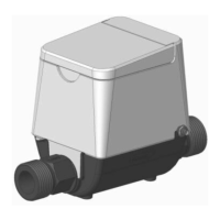
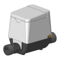
Counts water volume, offers CAT-M1 radio, optional BLE/infrared interfaces, and a push button for data display.

Certification Standards

CE marking confirms conformity with harmonized European standards, FCC, UL, and NSF.

Canadian Compliance

Complies with Canadian ICES-003 and RSS-247 rules for digital apparatus.

Radiation Exposure Statement

Complies with limits for uncontrolled environments; requires minimum 31cm distance from the body.

Product Overview Diagram

Diagram showing WAN radio antenna, PAN BLE antenna, optical port, water flow direction, and other components.

Meter Components and Interfaces

LCD Display Symbols

Explanation of LCD symbols for battery status, link quality, errors, application menus, air/leakage, and flow direction.

Front Panel Button Functionality

Single push button for menu navigation: long push to change menu, short push for next screen, double push to edit/validate.

Communication Ports Overview

All ports require proper identification. Desactivate radio before air transportation.

Infrared Communication Port

Optical port compatible with IrPHY SIR 115.2kb/s for reading and writing meter data.

Remote CAT-M1 WAN Radio

LTE 4G Cat-M1 radio communication port operating on bands 4 and 13.

Bluetooth Low Energy PAN Radio

BLE radio in 2.4-2.483 GHz band for reading and writing meter information.

Mounting Instructions

Installation Orientation and Alignment

Install in any orientation; arrow on pipe must match water flow direction. Ensure connection distance compatibility.

Proper Mounting Procedure

Press rotating nut, engage thread by unscrewing slowly, then screw by hand and finish with a wrench (30 Nm max).

Lifetime Consideration

Product lifetime may not be achieved if installed horizontally with SMA connector downward.

Related product manuals