AT2112
1 GENERAL INFORMATION
1.1 INTRODUCTION
This section gives you all necessary information to make service of this unit down to component level.
1.2 PRINCIPLE OF OPERATION AND BLOCK DIAGRAM
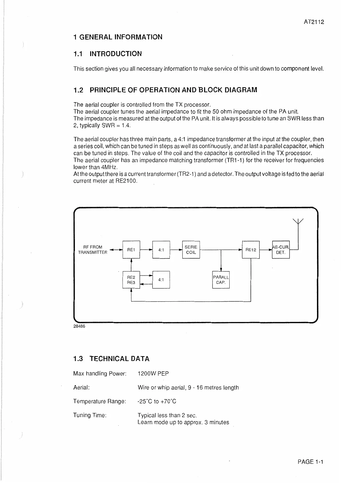
The aerial coupler is controlled from the
TX
processor.
The aerial coupler tunes the aerial impedance to fit the 50 ohm impedance of the PA unit.
The impedance is measured at the output of the PA unit. lt
is
always possible to tune an SWR less than
2,
typically SWR = 1.4.
The aerial coupler has three main parts, a
4:1
impedance transformer at the input at the coupler, then
a series coil, which can be tuned
in
steps
as
well
as
continuously, and at last a parallel capacitor, which
can be tuned
in
steps. The value of the coil and the capacitor
is
controlled in the
TX
processor.
The aerial coupler has
an
impedance matching transformer
(TR1
-1) for the receiver for frequencies
lower than 4MHz.
At the output there
is
a current transformer (TR2-1) and a detector. The output voltage is fed to the aerial
current meter at RE2100.
RFFROM
TRANSMITTER
28486
RE1
RE2
RE3
4:1
4:1
SERIE RE12
COIL
PARALL
CAP.
1.3 TECHNICAL DATA
Max handling Power:
1200W PEP
Aerial:
Wire
or
whip aerial, 9 - 16 metres length
Temperature Range: -25°C to +70°C
Tuning Time:
Typical less than 2 sec.
Learn mode up to approx. 3 minutes
E-CUR.
DET.
PAGE
1-1
 Loading...