This document provides a comprehensive guide for the Norton CV4E 40/L and CV4E 40/M antistatic vacuum cleaners, designed for both wet and dry applications. It emphasizes safety, proper usage, and maintenance procedures to ensure optimal performance and user safety.
Function Description:
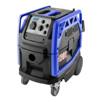
The Norton CV4E 40/L and CV4E 40/M are professional wet and dry vacuum cleaners. They are designed to collect both solid dust and liquids, making them versatile for various cleaning tasks. The "ANTISTATIC" designation indicates features to prevent static electricity buildup during operation, which is crucial when dealing with certain types of dust or in specific environments. The devices are classified for different levels of hazardous dusts: Class L (Light Risk), Class M (Medium Risk), and Class H (High Risk). The Class H model is noted as not available for Norton Vacuum.
Important Technical Specifications:
- Voltage - Frequency: 220 - 240 V~ 50/60 Hz
- Maximum Power (Suction): 1350 W
- Nominal Power (Suction): 1100 W
- Power Load Electrical Socket: 2400 W
- Total Power Σ: 3500 W
- Sound Pressure (LpA): 73.4 dB(A)
- Uncertainty (KpA): 2.5 dB(A)
- Vibration Level: < 2.5 m/s²
- IP Code: IPX4 (protection against solid objects larger than 1mm and splashing water from any direction)
- Filtering Surface of the Main Filter: 0.5 m²
- Air Flow: 273.6 m³/h
- Suction: 250 hPa
- Container Capacity: 41 l
- Useful Capacity: 26 l
- Useful Capacity Fleece Bag: 20 l
- Supply Cable Length: 7 m
- Dimensions (Length x Width x Height): 625 x 385 x 545 mm
- Weight (without accessories): 21 kg
- Suction Hose Diameter: Ø 33 mm
- Class M and Class H Suction Tube Diameters: Ø 21 - Ø 29 - Ø 33 - Ø 38 mm
- Filtering Surface Class H Filter: 0.8 m² (for Class H models, if available)
Usage Features:
The vacuum cleaner is equipped with several features to enhance usability and safety:
- Main Power Switch (27 Fig. O): This multi-position switch controls the vacuum's operation.
- "O" position: Electrical tool socket (17 Fig. J) is live, but the suction unit is off.
- "I" position: Suction unit is always on.
- "AUTO" position: Suction unit starts when the connected tool is activated.
- "Filter Cleaning" position: When combined with the automated filter cleaning switch (28 Fig. O) on "ON", it initiates intensive filter cleaning (3 blasts and maximum suction power).
- "NONSTOP VAC!" Filter Cleaning Switch (28 Fig. O): This system automatically cleans the filter during operation to maintain optimal suction and filtration. When set to "ON" and combined with the main power switch in "I" or "AUTO" mode, it performs 3 blasts at startup and 1 blast every 12 seconds. Setting it to "OFF" disables this function.
- Suction Power Adjustment Switch (29 Fig. O): Allows the user to increase or decrease the suction power.
- Suction Tube Diameter Switch (30 Fig. O): For Class M and H devices, this switch must be set to match the diameter of the flexible tube used to ensure correct air suction speed.
- LED Warning Lights:
- Cartridge Filter LED Warning Light (31 Fig. O): For Class H devices, a flashing light indicates a problem with the filter, requiring troubleshooting.
- Suction Unit LED Warning Light (32 Fig. O): For Class M and H devices, a flashing light indicates that the air speed in the tube is ≤ 20 m/s, requiring troubleshooting.
- Mobility: The device is fitted with wheels and can be moved using ergonomic handles on the head unit or pushed with the optional handle (22 Fig. K). A brake control (25 Fig. M) on the castor wheels allows for locking the device in place.
- Tool Connection:
- Power Tool Connection: An electrical socket (17 Fig. J) on the head unit allows for connecting power tools (max 2400 W).
- Pneumatic Tool Connection (Optional): For models with pneumatic fittings, a hose (18 Fig. J) from a pneumatic tool can be connected to the vacuum's fitting (19 Fig. J). A pneumatic power supply line (20 Fig. J) can also be connected to a fitting (21 Fig. J) on the vacuum (max 10 bar).
- Ergonomic Handle (11 Fig. E): Allows for adjusting suction force via a knob (14 Fig. I) and a window (15 Fig. I) for reduced suction.
- Accessories: Various accessories like extension tubes (12-13 Fig. G), suction nozzles, brush attachments, and crevice tools (13 Fig. H) can be attached. A reduction sleeve can also be installed on the flexible tube (10 Fig. E).
Maintenance Features:
Regular cleaning and maintenance are essential for the longevity and safe operation of the vacuum cleaner.
- Safety First: Always unplug the appliance from the electrical socket before performing any maintenance. Operations involving hazardous dust must only be carried out by authorized and trained personnel wearing suitable personal protection.
- Fleece Dust Bag Removal and Replacement (if present):
- Release levers (1 Fig. A) and remove the head unit (2 Fig. B).
- Check for the fleece filter bag (4 Fig. C) in the waste container (3 Fig. B).
- If absent, slot the bag onto the nozzle (5 Fig. C) over the neck (6 Fig. C) and arrange it in the waste container.
- Remove the used bag and dispose of it according to local regulations.
- Replace with a new fleece bag and reassemble.
- Waste Container Emptying:
- Release levers (1 Fig. A) and remove the head unit (2 Fig. B).
- Place the vacuum over a drain and lift the waste container (3 Fig. Q) using the handle (35 Fig. Q) until empty.
- Clean the inside of the container with clean water and dry it.
- Reassemble all parts.
- Main Filter Checking and Cleaning:
- Raise the rear door (36 Fig. R) using the lever.
- Remove the main filter (37 Fig. R).
- Clean the filter with a jet of air from the inside outwards. It can be washed with warm water and reassembled only when completely dry. Replace if dirty or worn.
- Put the filter back in its slot and close the rear door.
- Appliance Cleaning:
- Clean the unit body with a cloth dampened with water or a mild detergent.
- Remove the head unit and clean the waste container with running water, then empty it.
- Reassemble all parts.
- DANGER: Do not wash the appliance using jets of water.
- Class H Cartridge Filter Replacing (if applicable):
- Release levers (1 Fig. A) and remove the head unit (2 Fig. B).
- Turn the head unit upside down.
- Unscrew four screws (38 Fig. S) and remove the filter cover (39 Fig. S).
- Remove the cartridge filter (40 Fig. S) and dispose of it according to regulations.
- Replace with a new cartridge filter and reassemble.
- WARNING: Debris on the filter and the filter itself must be disposed of according to national standards.
- Water Level Sensors Cleaning:
- Release levers (1 Fig. A) and remove the head unit (2 Fig. B).
- Turn the head unit upside down.
- Clean the water level sensors (41 Fig. S) and check for wear.
- Reassemble all parts.
- Vacuum Motor Filter Checking and Cleaning:
- Release two catches (42 Fig. T) and remove the cover (43 Fig. T).
- Remove the sponge filter (44 Fig. T).
- Clean the sponge with a jet of air (45 Fig. T). It can be washed in warm water and replaced only when completely dry. Replace if too dirty.
- Reassemble all parts.
- Periodic Inspections: The manufacturer or a trained person should inspect the appliance at least once a year to check the filtration system, air flow, and control system. Class H machines require an annual filtration system test according to standard 60335-2-69 chap. 22.AA.201.2. If the test fails, the Class H filter must be replaced and retested.
- Decontamination: For Class M and H machines, the exterior must be decontaminated using a vacuum, cloth, or sealant before leaving the danger area. All machines are considered decontaminated once they leave the danger zones and measures are taken to prevent dust dispersion.