The SAKER Fiber Optic Isolated Current Probe (HVCP) is a novel AC current probe designed for high voltage isolation via fiber optic cables. It offers an advantageous approach to voltage isolation, making it immune to typical radiated interferences and capacitances created when using long coaxial measuring cables. The current sensor is a Rogowski coil, which is small, lightweight, and can be tied around conductors without breaking the current path. Both the probe head and handheld receiver are battery powered. The receiver features a proprietary output connector and can be connected to any oscilloscope or measuring instrument via a standard BNC connector.
Function Description
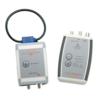
The HVCP system consists of a probe head and a handheld receiver, connected by two fiber optic cables. The probe head, which contains the Rogowski coil, is placed around the conductor to be measured. The receiver processes the signal from the probe head and provides an output suitable for an oscilloscope or other measuring instrument. The fiber optic connection ensures excellent isolation between the probe head and receiver, allowing measurements in high voltage environments.
Important Technical Specifications
The HVCP series offers various models with different current ranges and bandwidths. The bandwidth for all models is 2Hz to 2MHz. Maximum measurable currents vary by model: HVCP2000 measures up to 2000A, HVCP1000 up to 1000A, and HVCP500 up to 500A. The overall accuracy is ±2%. The receiver output connector is BNC, with a receiver output range of ±5V. The output ratio varies by model: 2.5 mV/A for HVCP2000, 5 mV/A for HVCP1000, and 10 mV/A for HVCP500. The measuring instrument minimum input impedance is 200 kΩ. Calibration time is 3 seconds.
The output noise is 3 mV rms. The receiver power, normal mode, is 100 mW, and in standby mode, it is 20 mW. The probe head power, normal mode, is 380 mW, and in standby mode, it is 20 mW. Both the probe head and receiver are powered by 2x1.5V AAA type batteries. The Rogowski enclosed circular conductor diameter is 71 mm, and the planar busbar dimensions are 100x10 mm. The working temperature range is -20 to +60 °C, with a maximum operating humidity (non-condensing) of 85%. The fiber optic bundle length is 3m standard, with other options available.
The device complies with EMC IEC 61326-1:2012, ESD 61000-4-2 (A), RF 61000-4-3 (A), Safety IEC 61010-1, 61010-030, RoHS 2011/65/EU normative references.
Usage Features
- Calibration: A calibration feature ensures accurate measurements by adjusting the fiber optic link to minimize measurement errors due to temperature drifts or offsets. The probe automatically checks for typical 50/60Hz noise seen in many Rogowski current probes. Calibration is performed by pressing the CAL button on the receiver. A short blink of the CAL LED indicates successful calibration.
- Turning On/Off: To turn on either the probe head or the receiver, press the TURN ON button until the ON LED lights. A short press turns on the units. If the unit fails to turn on, check if the batteries are dead and replace them. The probe head cannot be turned on remotely. To turn off, press the TURN ON button for 1 second on either unit. If fiber optic cables are connected, both units will turn off.
- Standby Mode: This mode places both the probe head and receiver in a low power state for extended battery duration. It is recommended to use this feature when the probe is not in use. To enter standby mode, press the TURN ON button shortly in either unit. The ON green LED will start blinking. If the fiber cables are connected, the other unit will also enter low power mode. To return to normal mode, press the TURN ON button shortly in either unit.
- Fiber Optic Connections: The probe head and receiver are connected with two fiber optic cables supplied in a bundle, differentiated by yellow and red strip markers. Each connector uses a bayonet type connector that requires a small twist to be properly fixed. It is crucial to protect the optical connectors from dust with the supplied protective covers when not in use. Do not twist or bend the fiber optic cable at sharp angles; the minimum bending radius is 6 cm.
- Probe Placement: The probe head uses a Rogowski coil as its measuring element. The conductor to be measured must be placed inside the coil. An arrow on top of the coil sensor indicates the positive sign of the passing current. Currents flowing in the opposite direction will measure as negative voltages in the HVCP receiver.
- Safety: The HVCP probe head is not a handheld instrument and should be considered to be floating at the same potential of the current-carrying conductor. It is advisable to install a voltage detector/indicator on the measured line that provides visual and clear indication about the presence of potentially dangerous voltages. SAKER offers the MVD and MVDH series of medium voltage presence detectors.
- Receiver-Oscilloscope Connection: A BNC-BNC cable is supplied to connect the receiver to a measuring oscilloscope.
Maintenance Features
- Battery Replacement: Both units use standard 1.5V AA batteries. To replace the batteries, open the back cover of the respective unit. The HVCP10 probe head requires the use of a small Phillips head screwdriver to open the back cover. Follow the polarity sign to replace the batteries and close the cover afterwards. Remove the batteries from inside the equipment if it is to be stored for more than 5 months.
- Low Battery Condition: The BATT LOW LED on the receiver and probe head indicates the battery status. One blink means the batteries at the HVCP probe head should be replaced. Two blinks mean the batteries at the HVCP receiver should be replaced. Three blinks mean the batteries at both the HVCP receiver and remote probe should be replaced.
- Customization: SAKER offers customization services for this product. Typically, an end user may need a different current measuring range, a special increased fiber optic cable length between the probe head and handheld receiver unit, or a higher capacity battery pack to power the remote probe head for long-term measurements.