This document describes the EC-Drain 2x4.0 electronic switchgear, a microcontroller-integrated device designed for automatic control of two pumps. The original operating instructions are in German, and this document provides a translation into English.
Function Description
The EC-Drain 2x4.0 controls two pumps based on the switching status of connected float switches. When a high water level is reached, the device outputs an optical and acoustic signal and initiates a forced pump switch-on. Both collective fault signals and high water alarms are active. An optional rechargeable battery (accessory) allows for a mains-independent alarm signal, indicating a missing mains voltage with a continuous acoustic signal. Pump faults are registered and evaluated, with operating statuses displayed by LEDs on the front panel. Operation is managed via buttons on the right side of the housing.
After connecting to the supply voltage or following any mains interruption, the switchgear returns to its previously set operating mode. All LEDs illuminate for approximately 2 seconds for testing purposes before the device becomes operational.
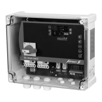
Operating Elements (Fig. 1):
- Main Switch (4-pole): Controls the power (0 = OFF, I = ON).
- Manual Mode Button (pos. 1): Activates Pump 1 or Pump 2 independently of the float switch signal. All safety functions, such as electronic motor protection and WSK winding protection monitoring, remain active. The green "Pump 1 operation" (pos. 6) or "Pump 2 operation" (pos. 10) LED stays on as long as the button is pressed. This mode is intended for commissioning or testing and is active only while the button is held.
- Stop Button (pos. 2): Deactivates automatic mode for both pumps, causing the green LEDs (pos. 5, pos. 9) to flash. No automatic pump activation occurs. If the high water level is reached, optical and acoustic alarms are issued, and the collective fault signal (SSM) and high water alarm contacts become active.
- Automatic Mode Button (pos. 3): Activates automatic mode for both pumps based on DIP switch settings 6 and 7 (Fig. 2, pos. 3). The green LEDs (pos. 5, pos. 9) remain permanently on. If a pump is deactivated via DIP switches, its corresponding LED stays off. In automatic mode, pumps are controlled by float switch signals. When the first activation point is reached, the base-load pump switches on. The peak-load pump cuts in at the second activation point. The green LEDs (pos. 6, pos. 10) are on during pump operation. When the base-load float switch deactivation point is reached, the peak-load pump switches off, and the follow-up time (Fig. 2, pos. 2) for the base-load pump begins. The green LEDs flash until the set time elapses, after which the base-load pump switches off. Pumps are cycled after each base-load pump shutdown to optimize running times. All pump safety functions (electronic motor protection, WSK monitoring) are active in automatic mode. In case of a pump fault, the system automatically switches to the functional pump, issues optical and acoustic signals, and activates the collective fault signal (SSM). High water level also triggers optical/acoustic alarms, SSM, and forced pump switch-on for increased safety.
- Buzzer Off/Reset Button (pos. 4): Briefly pressing this button after an error occurs deactivates the built-in buzzer and acknowledges the collective fault signal relay. To acknowledge the fault and re-enable control, the button must be pressed for at least half a second. A fault can only be acknowledged once it and its cause have been remedied.
Fault Memory: The control unit includes a non-volatile error memory. The last fault can be displayed by simultaneously pressing "stop" + "auto" buttons. To erase the error memory, simultaneously press "Manual 1" + "stop" for approximately 1 second.
Display Elements (Fig. 1):
- Ready for Operation (pos. 15): Green LED is permanently lit when power and control voltage are supplied.
- Automatic Mode (pos. 5, pos. 9): Green LED flashes if control voltage is applied but automatic mode is deactivated; it is lit when automatic mode is active; it is off if the pump is deactivated via a DIP switch.
- Operation (pos. 6, pos. 10): Green LED is lit when the pump is switched on (activation level reached); it flashes green if the pump is switched on by the set follow-up time.
- High Water (pos. 14): Red LED is lit when the high water alarm is triggered.
- Overload Fault (pos. 7, pos. 11): Red LED is lit if the electronic excess current release is triggered (set via DIP switches 1-5, see Section 6.2.3); it flashes red if the control is operated without a load.
- Winding Fault (pos. 8, pos. 12): Red LED is lit if the thermal winding contact (WSK) is triggered.
- Service (pos. 13): Yellow LED is lit when the service interval set via DIP switches 4 and 5 (Fig. 2, pos. 3) expires. Maintenance is recommended to increase operational reliability. The counter must be reset by qualified personnel.
- Incorrect Phase Sequence (3~ version only): All LEDs flash anti-clockwise in sequence, an acoustic alarm is issued, and the collective fault signal (SSM) is active.
Important Technical Specifications
DIP Switches (Fig. 2, pos. 1, above potentiometer):
- Internal Electronic Motor Protection (DIP 1-5): Sets the excess current release according to the nominal pump current (1.5-12 A). Deactivation occurs if the set nominal pump current is exceeded or if the current falls below 300 mA when the pump is on for more than 1 second. After each release, the fault must be acknowledged with the Reset button. If DIP switches 1-5 are OFF, the lowest current value of 1.5 A is set. If any DIP switches are ON, their corresponding values (0.5 A, 1.0 A, 2.0 A, 3.0 A, 4.0 A) are added to the 1.5 A base value.
- Test Run (DIP 6): Activates/deactivates a cyclical 2-second test run after 24 hours of pump downtime to prevent long idle times.
- Buzzer (DIP 7): Activates/deactivates the internal buzzer. If voltage drops or the main switch is off, the buzzer cannot be deactivated via the DIP switch; the rechargeable battery (accessory) must be removed if necessary.
DIP Switches (Fig. 2, pos. 3, below potentiometer):
- Mains Voltage Setting (DIP 1): Sets the mains voltage (3~400 V or 1~230 V). Incorrect setting can damage the switchgear.
- Spare/Unassigned (DIP 2-3): Reserved.
- Service Interval (DIP 4-5): Sets the service interval (quarterly, semi-annually, annually). If both are OFF, no service is displayed. An optical signal (yellow LED) is issued when the interval expires.
- Pump Activation (DIP 6-7): Activates/deactivates Pump 1 and Pump 2. If a pump is off, it will not be switched on by a float switch request.
Follow-up Time (Fig. 2, pos. 2): Adjustable potentiometer (0-120 seconds) for the base-load pump's follow-up time after the float switch contact opens.
External Motor Protection (WSK): If the motor has a thermal winding contact (WSK), it must be connected to terminals 1 and 2 for Pump 1, and 3 and 4 for Pump 2. For motors without WSK, a jumper must be installed.
High Water Alarm: A float switch connected to terminals 9 and 10 (HW) triggers optical/acoustic signals and forced pump switch-on. Collective fault (SSM) and high water alarm are active.
Usage Features
Installation and Electrical Connection:
- The switchgear must be installed in a dry, vibration-free, and frost-proof location, protected from direct sunlight.
- Borehole distances: 268 x 188 mm (WxH).
- Electrical connections must be performed by qualified electricians according to local regulations.
- Mains supply voltage, current, and type must match the pump/motor rating plate.
- Fuse protection (max. 25 A, slow-blow) and a residual-current-operated protection switch with K characteristic are required on the mains side.
- Cable ends must be fed through threaded cable connections and wired according to terminal strip markings. After tightening, ensure cables are firmly fixed; use reducer seals if necessary.
- The pump/installation must be earthed.
- Mains Connection 1~230 V (L, N, PE): Switchgear terminals 2/T1, N, PE. Pumps terminals 4/T2, 6/T3, PE.
- Mains Connection 3~400 V (L1, L2, L3, PE): Switchgear terminals 2/T1, 4/T2, 6/T3, PE. Pumps terminals 2/T1, 4/T2, 6/T3, PE. Connect clockwise rotating field to mains terminals.
- Signal Contacts:
- SSM (terminals 11, 12, 13): External collective fault signal, potential-free changeover contact (min. 12 V DC, 10 mA; max. 250 V~, 1A). Contact closes between 12 and 13 on alarm, voltage drop, or main switch off.
- Alarm (terminals 14, 15, 16): External high water alarm, potential-free changeover contact (min. 12 V DC, 10 mA; max. 250 V~, 1A). Contact closes between 15 and 16 on alarm.
- GL (terminals 5, 6): Float switch for base-load pump.
- SL (terminals 7, 8): Float switch for peak-load pump.
- HW (terminals 9, 10): High water float switch and forced pump switch-on.
- WSK Pump 1 (terminals 1, 2): Motor protection WSK for Pump 1. Remove factory-installed bridge if WSK is connected.
- WSK Pump 2 (terminals 3, 4): Motor protection WSK for Pump 2. Remove factory-installed bridge if WSK is connected.
Commissioning:
- All settings (mains voltage, DIP switches, nominal pump current, follow-up time) must be checked before commissioning.
- Establish mains connection and switch on the unit.
- Direction of Rotation Monitoring (3~ version only): If the phase sequence is incorrect, an acoustic signal and flashing LEDs (anti-clockwise) indicate this, and the collective fault signal is active. Automatic start-up or manual switching is not possible. Exchange two phases if incorrect.
- Rechargeable Battery (accessory): Insert the battery into its holder, ensuring correct polarity. Secure with the provided cable tie. The battery must be fully charged (24 hours in the switchgear) at commissioning.
Maintenance Features
General Maintenance:
- Maintenance and repair work must be carried out by qualified personnel.
- The system must be voltage-free and secured against unauthorized switch-on.
- Electrical work must be performed by qualified electricians.
- Maintenance intervals for sewage lifting units (EN 12056-4):
- Commercial: every 3 months.
- Multi-family houses: every 6 months.
- Single-family houses: annually.
- Visual inspection of electrical components is required.
- A maintenance report must be compiled.
- A maintenance plan helps prevent costly repairs and ensures fault-free operation.
Troubleshooting (Faults, Causes, Remedies):
- LED lit red (Overload): Electronic excess current release triggered.
- Remedy: Check pump and DIP switch settings, power supply. Reset LED display with Reset button.
- LED flashing red (Low Current/Missing Phase): Pump current below 300 mA or L phase missing.
- Remedy: Check power supply, pump, and pump cable. Reset LED display with Reset button.
- LED lit red (Winding Fault): WSK triggered or bridge missing at WSK terminals.
- Remedy: Check pump and wiring.
- LED lit red (High Water Alarm): High water alarm signal.
- Remedy: Check system/pump.
- All LEDs flashing anti-clockwise (Incorrect Phase Sequence): Incorrect phase sequence.
- Remedy: See direction of rotation monitoring under commissioning.
If operating faults cannot be remedied, consult a skilled craft firm or Salmson customer service.
Spare Parts: Ordered via local specialist retailers or Salmson customer service. All rating plate details must be provided for each order.
Disposal: Proper disposal and recycling prevent environmental damage and health risks. Contact public or private waste management companies, local council, or supplier for detailed information.