Do you have a question about the Salus KL08NSB and is the answer not in the manual?
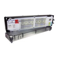
Explains the KL08NSB wiring centre's role in underfloor heating control systems.
Lists EU Directives and provides a link for the Declaration of Conformity.
Details safe usage, indoor-only installation, and precautions against water damage.
Provides specifications such as power supply, load limits, inputs, outputs, and dimensions.
Explains the main fuse, its location, type, and replacement procedure.
Details the 230 V AC 50Hz power supply and required two-wire installation.
Describes the NSB function activation via external signal and thermostat wiring.
Illustrates four options for applying the NSB function with master thermostats or external clocks.
Explains how to select the actuator type (normally closed or open) using a jumper.
Details the delay jumper for boiler off-time and its effect on pump/boiler operation.
Explains the volt-free output that controls the boiler in the heating system.
Describes the volt-free output that controls the circulation pump in heating/cooling.
Details how to connect thermoelectric actuators to the wiring centre zones.
Explains the serial connector for linking with the KL04NSB extension module.
Describes the reset button's use for refreshing data after jumper changes.
Illustrates connecting various thermostat types (Expert, 230V, battery-powered).
Instructions for removing covers, unscrewing the housing, and mounting to a wall or DIN rail.
Details the required insulation stripping length for different wire types.
Guides on threading wires through the wiring centre and connecting them to terminals.
Instructions for connecting actuators, securing the housing, and powering up the unit.
The Salus KL08NSB is an 8-zone 230V wiring centre designed to be the central component of an underfloor heating control system. It facilitates the easy and quick connection of thermostats and actuators, offering integrated pump and boiler control, as well as overload protection. The KL08NSB is adaptable to work with both normally closed (NC) and normally open (NO) type actuators. It can connect up to 8 thermostats, and with the addition of a KL04NSB extension module, the system can support up to 12 thermostats in total.
The wiring centre manages the heating system by receiving signals from connected thermostats and controlling the pump and boiler accordingly. It features a Night Set Back (NSB) reduction function, which allows non-programmable Salus thermostats (Expert NSB, HTR, BTR series) to reduce their setpoint temperature by switching to eco mode. This function is activated via an external 230V signal from a timer or programmable thermostat connected to the KL08NSB. Thermostats for NSB functionality must be connected using a 4-wire cable (minimum 4 x 0.75 mm², maximum 4 x 1.5 mm²).
The NSB function offers several grouping options:
The wiring centre also includes a delay function for the boiler and pump. The pump and boiler always start 3 minutes after receiving a heating signal from any connected thermostat. The pump stops 3 minutes after the last call for heating from a thermostat. The heat source (boiler) turns off after the time set on the Delay jumper.
The device must be used in accordance with national and EU regulations and is intended for indoor use only in dry conditions. Installation must be carried out by a qualified person. Before setup and installation, ensure the KL08NSB is disconnected from any power source. Incorrect installation can damage the wiring centre. The KL08NSB should not be installed in areas exposed to water or damp conditions.
The KL08NSB complies with essential requirements and provisions of EU Directives: EMC 2014/30/EU, LVD 2014/35/EU, and RoHS 2011/65/EU. The full text of the EU Declaration of Conformity is available on www.saluslegal.com.
| Brand | Salus |
|---|---|
| Model | KL08NSB |
| Category | Control Systems |
| Language | English |