12 | SAMLEX AMERICA INC. SAMLEX AMERICA INC. | 13
SECTION 5 | Installation & Charger Operation
be disabled to prevent overcharging of the battery (see details under
CAUTION!
at Section 4.1.3). A DIP Switch (4 in Figs 2.1 to 2.3) is provided on top of the output
terminals for selecting the battery type and for disabling the Boost Stage when charging
loaded batteries. The following selections can be made with the help of the DIP Switch.
CAUTION!
Do not change the DIP Switch setting when the charger is operating. Always
change the DIP Switch setting when the charger is off , i.e. after disconnecting
the charger from the AC input power.
NOTE: The voltages are for a temperature of 80°F.
CAUTION!
Please ensure that the position No. 4 of the DIP switch (S1-ON & S2-ON) is
NEVER selected.
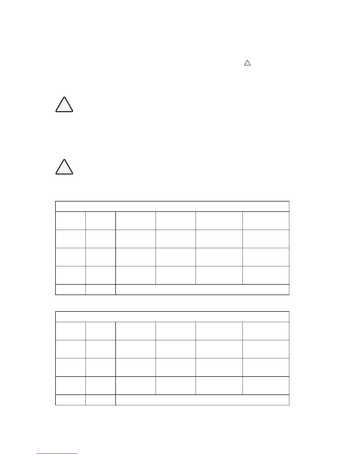
TABLE 5.1 DIP SWITCH SETTINGS: SEC-1215UL/SEC-1230UL
S1 S2 Float Boost
Battery
Type
Charging
Stages
OFF * ON * 13.5 V * 14.4 V * Flooded /
AGM *
3 Stages
(Stages 1, 2, 3)
ON OFF 13.5 V 14.0 V Gel Cell 3 Stages
(Stages 1, 2, 3)
OFF OFF 13.5 V Disabled Battery with
Load
2 Stages
(Stages 1, 3)
ON ON Caution! Do NOT use this setting
* Factory pre-set in this position
TABLE 5.2 DIP SWITCH SETTINGS - SEC-2415UL
S1 S2 Float Boost
Battery
Type
Charging
Stages
OFF * ON * 27 V * 28.8 V * Flooded /
AGM *
3 Stages
(Stages 1, 2, 3)
ON OFF 27 V 28.0 V Gel Cell 3 Stages
(Stages 1, 2, 3)
OFF OFF 27 V Disabled Battery with
load
2 Stages
(Stages 1, 3)
ON ON Caution! Do NOT use this setting
* Factory pre-set in this position