44_ installing your air conditioner
Indoor Unit Installation
It is recommended to install the Y- joint before installing the indoor
unit.
1.
Place the pattern sheet on the ceiling at the spot where you
want to install the indoor unit.
Since the diagram is made of paper, it may shrink
or stretch slightly due to temperature or humidity.
For this reason, before drilling the holes maintain
the correct dimensions between the markings.
Note
2.
Insert bolt anchors, use existing ceiling supports or construct a
suitable support as shown in figure.
Concrete
Suspension bolt(
Ø9.52 or M10)
Hole in anchor
Hole in plug
Insert
3.
Install the suspension bolts depending on the ceiling type.
Ensure that the ceiling is strong enough to support
the weight of the indoor unit. Before hanging the
unit, test the strength of each attached suspension
bolt.
If the length of suspension bolt is more than 1.5 m, it
is required to prevent vibration.
If this is not possible, create an opening on the false
ceiling in order to be able to use it to perform the
required operations on the indoor unit.
Ceiling support
4.
Screw eight nuts to the suspension bolts making space for
hanging the indoor unit.
You must install the suspension bolts more than four
when installing the indoor unit.
Nut
Washer
Rubber
Fasten the nut
CAUTION
CAUTION
5.
Check the level of the indoor unit by using a leveler.
A tilt of the indoor unit
may cause malfunction of
a built-in float switch and
water leaks.
Level
6.
Adjust the height of the indoor unit by using the gauge of
dimensions.
You should adjust the jigs and the pattern sheet to fit the
cutting dimensions of ceiling.
Noise may occur if you do not adjust the location of the indoor
unit according to location of the jigs during installation.
- Adjust the location of the indoor unit according to the jigs.
Make sure that the indoor unit is installed at a level if the
indoor unit slants too much, there can be water leaks.
AM✴✴✴HN1DEH✴ models have installation guide on the
product. Make sure to adjust the height of the suspension bolt
so that surface of the ceiling and the installation guide on the
indoor unit is parallel to each other.
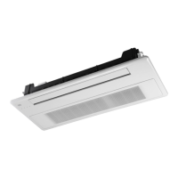
Slim 1 way cassette
Side view
Air inlet Air outlet
15 mm
15 mm
Jig
Ceiling
AMFN1DEH/AMJN1DEH AMHN1DEH
❇ Make sure surface of the ceiling and the installation
guide is parallel to each other.
135 mm
155 mm
Installation guide
Location of the installation guide
45mm 45mm
CeilingCeiling
Ceiling
17mm
20 m
m
Indoor unit
Jig
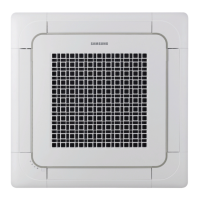
2 way cassette 4 way cassette
AMFN2DEH AMFN4DEH
7.
Tighten the upper part nuts.
8.
Remove the gauge of dimensions after installing the indoor
unit.
Performing Leak Test & Insulation
g The designs and shape are subject
to change according to the model.
LEAK TEST WITH NITROGEN(before opening valves)
In order to detect basic refrigerant leaks, before recreating the
vacuum and recirculating the R-410A, it’s responsible of installer
to pressurize the whole system with nitrogen(using a pressure
regulator) at a pressure above 4.1MPa(gauge).
LEAK TEST WITH R-410A(after opening valves)
Before opening valves, discharge all the nitrogen into the
system and create vacuum. After opening valves check leaks
using a leak detector for refrigerant R-410A.
Leak test
Discharge all the nitrogen to create a vacuum and
charge the system.
Installation Part
Leak check
NASA_Cassette type_IB_EN_03568A-07.indd 44 2016-04-06 오전 9:01:17
 Loading...