Do you have a question about the Samsung AM032MNQDCH/AA and is the answer not in the manual?
Guidelines for safe service procedures, including part usage and connections.
Measures against static electricity and handling of sensitive components.
General safety precautions for electrical handling and operation.
Safety and environmental guidelines for handling refrigerant.
Safety measures and procedures for welding refrigerant pipes.
Guidelines for accurately adding refrigerant to the system.
Additional safety instructions for installation and operation.
Detailed technical specifications for the air conditioning system.
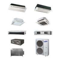
Technical specifications specifically for indoor units.
Specifications for the Slim 1WAY cassette indoor unit models.
Specifications for optional accessories and system add-ons.
Procedures for disassembling and reassembling indoor units.
Disassembly steps for the Slim 1-way cassette indoor unit.
Disassembly procedures specific to BIG DUCT indoor units.
Disassembly steps for Global 4way Cassette indoor units.
Disassembly procedures for Wall Mounted type (A3050, MAX) units.
Disassembly steps for 360 Cassette indoor units.
Explanation of the check-up window on the main PCB for error diagnostics.
Details on special operational modes for service technicians.
General guidance and methods for troubleshooting issues.
Specific measures to address various operational symptoms and errors.
Detailed PCB diagrams and parts lists for various indoor unit types.
PCB layout and component identification for Slim 1-way cassette units.
PCB layout for 4-way and mini 4-way cassette indoor units.
PCB layout for SLIM Duct 1,2 indoor units.
PCB layout for Slim Duct 3, MA-1 indoor units with drain pump.
PCB layout for MSP, HSP Small, BIG Duct, MA-2 indoor units.
PCB layout for Ceiling type indoor units.
PCB layout for Big Ceiling indoor units.
PCB layout for Wall-Mounted (Neo Forte) indoor units.
PCB layout for Wall Mounted (A3050, MAX) indoor units.
PCB layout for Wall Mounted (Boracay) indoor units.
PCB layout for Floor Stand Type indoor units.
PCB layout for OAP DUCT indoor units.
PCB layout for Global Duct -1,2 indoor units.
PCB layout for Global Duct -3 indoor units.
PCB layout for Wind-free 1way cassette indoor units.
PCB layout for 360 Cassette indoor units.
Diagram and parts list for the Indoor Unit Power PCB.
PCB diagram for the Display unit.
Wiring diagrams for various indoor unit types.
Wiring diagram for Global 4way/Mini 4way cassette indoor units.
Wiring diagram for Slim 1way cassette indoor units.
Wiring diagram for BIG Duct indoor units.
Wiring diagram for Ceiling type indoor units.
Wiring diagram for Big Ceiling units (AM036/048JNCDCH/AA).
Wiring diagram for RAC (Neo Forte) indoor units.
Wiring diagram for Wall Mounted type (A3050, MAX) units.
Wiring diagram for DUCT type (Slim Duct 3, MA-1) indoor units.
Wiring diagram for DUCT type (Slim Duct 1,2, MSP) indoor units.
Wiring diagram for DUCT type (HSP Small, MA-2) indoor units.
Wiring diagram for Floor Stand Type indoor units.
Wiring diagram for OAP Duct indoor units.
Wiring diagram for Wall-Mounted type (Boracay) indoor units.
Wiring diagram for Global Duct -1,2 (AM...MNMDCH/AA) indoor units.
Wiring diagram for Global Duct -3 (AM...MNMDCH/AA) indoor units.
Wiring diagram for Wind-free 1way cassette indoor units.
Wiring diagram for Wind-free 1way cassette units (continued).
Wiring diagram for 360 Cassette indoor units.
An index to help identify indoor unit and panel model names.
Index for identifying various indoor unit model codes.
Procedures and precautions for refrigerant pump-down operations.
Essential safety precautions before performing pump-down.
Pump-down procedure for systems with a single outdoor unit.
Pump-down procedure for systems with multiple outdoor units.
Instructions for safely transferring refrigerant into a container.
Procedure for transferring refrigerant before pump-down.
| Brand | Samsung |
|---|---|
| Model | AM032MNQDCH/AA |
| Category | Air Conditioner |
| Language | English |