23
7. Electrical Wiring Diagram
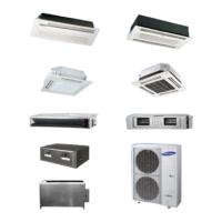
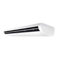
Wind-Free 1Way Cassette
• AM017/022NN1PEH/∗∗, AM056/071NN1DEH/∗∗
F100 FUSE EEV Electronic expansion valve EVA-IN(10K) Thermistor EVA IN(10K)
M[HALL IC] Motor (IDU fan) SPI S-Plasma ion
EVA-OUT(10K)
Thermistor EVA OUT(10K)
Thermal Fuse
Terminal Block thermal fuse
ROOM(10K) Thermistor ROOM(10K)
NOTE
• This wiring diagram applies only to the indoor unit.
• Symbols show as follow :
BLK: black, RED: red, BLU: blue, WHT: white, YEL: yellow, BRN: brown, SKY: sky blue, GRN: green
• For connection wiring indoor-outdoor transmission F1-F2, indoor-wired remote controller transmission F3-F4.
•
Protective earth(SCREW)
 Loading...