Do you have a question about the Samsung AQV09NSAX and is the answer not in the manual?
Lists key features like High Energy Efficiency, Simple Flat Grille, Good'sleep, Multi-functional Cleaning, and Silence Mode.
Covers safe installation practices, power supply, and circuit breaker requirements.
Guidelines for safe operation, including avoiding liquids and proper ventilation.
Information on disposing of the unit and general handling precautions.
Comprehensive table of specifications including performance, power, and size.
Comparison of key features and specs between different models.
Lists standard accessories for the indoor unit, e.g., remote control.
Lists accessories for the outdoor unit and items included in the accessory box.
Lists further accessories such as pipe clamps and insulation materials.
Instructions on how to enter and use the unit's test mode for diagnostics.
Table detailing indoor unit error indicators and corresponding checks.
Explanation of outdoor unit LED error displays and their meanings.
Step-by-step guide for setting various operational options using the remote.
Lists necessary tools like screwdrivers and spanners for disassembly.
Detailed steps for removing the indoor unit's front grille.
Steps for detaching the main PCB and removing the tray drain.
Procedures for removing the heat exchanger and fan motor.
Steps for removing the outdoor unit's side and front covers.
Procedures for removing rear and side panels to access internal components.
Steps to disconnect the outdoor control out assembly.
Procedures for removing fan motor, compressor, and valve assemblies.
Visual diagram of the indoor unit showing numbered parts.
Detailed list of indoor unit components with part codes and descriptions.
Visual diagram of the outdoor unit showing numbered parts.
Detailed list of outdoor unit components with part codes and descriptions.
Exploded view and parts list for the Ass'y Control In module.
Exploded view for the Ass'y Control Out module.
Parts list for the Ass'y Control Out module.
List of electronic components on the indoor main PCB.
Further electrical components for indoor PCBs and connectors.
Components for indoor sub and display PCBs.
List of electronic components on the outdoor main PCB.
Further electrical components for outdoor PCBs.
Components for the outdoor EMI PBA.
Diagram showing electrical connections for the indoor unit.
Diagram showing electrical connections for the outdoor unit.
Circuit schematic illustrating the indoor unit's internal circuitry.
Circuit schematic illustrating the outdoor unit's internal circuitry.
Explanation of the circuit blocks and functions of the indoor PCB.
Explanation of the circuit blocks and functions of the outdoor PCB.
Diagram showing the flow of refrigerant in the system.
Visual layout of components on the indoor PCB.
Visual layout of components on the outdoor PCB.
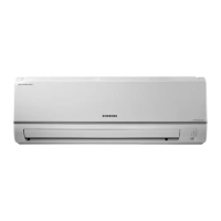
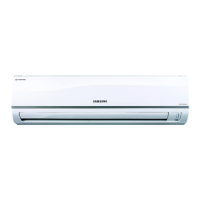
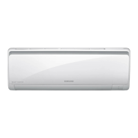
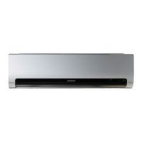
Labels for parts on the indoor unit's exterior.
Labels for parts on the outdoor unit's exterior.
Explanation of remote control buttons and display functions.
Details on Auto, Cool, Heat modes and fan speed selection.
Explanation of Dry, Fan, Turbo, and Good'sleep modes.
Preliminary checks for voltage, connections, and basic symptoms.
Step-by-step guide for units that do not power on.
Troubleshooting steps for outdoor unit power supply errors.
Diagnostic procedure for non-operational louvre motors.
Diagnostic steps for outdoor fan operational errors.
Diagnostic steps for errors related to total current trip.
Diagnostic steps for incorrect heating/cooling mode operation.
Diagnostic procedure for outdoor temperature sensor faults.
Diagnostic procedure for discharge temperature sensor faults.
Diagnostic procedure for coil temperature sensor faults.
Diagnostic procedure for general fan errors.
Diagnostic steps for DC-Link voltage sensor errors.
Diagnostic procedure for over current errors.
Diagnostic steps for communication errors between units.
Diagnostic procedure for compressor start failure.
Diagnostic procedure for compressor lock errors.
Diagnostic steps for DC Link over/low voltage errors.
Addresses remote control reception, zero cross signal, and capacity mismatch.
Safety notices and general procedures before inspecting PCBs.
Specific inspection steps for the indoor unit's main PCB.
Specific inspection steps for the outdoor unit's main PCB.
Methods for measuring resistance of key components like sensors and motors.
Diagram showing functional blocks and signal flow of the indoor unit.
Visual layout of components on the indoor PCB.
Diagram showing functional blocks and signal flow of the outdoor unit.
Visual layout of major components on the outdoor PCB.
Explanation of the coding system used for air conditioner model names.
Charts showing refrigerant pressure distribution based on temperatures.
Table for converting pressure and capacity units.
FAQs on cooling performance and leakage issues.
FAQs on smells, operational failures, and remote control issues.
Advice on installation location and windscreens.
Instructions for cleaning the unit and its air filters.
Procedure for cleaning optional deodorizing and bio filters.
Guidelines for site selection, unit fixing, and wall drilling.
Step-by-step guide for purging air from the system.
Procedure for pump down when replacing parts or relocating the unit.
Information on accessing Samsung's global service partner network.
| Compressor type | Rotary |
|---|---|
| Hose length (max) | 15 m |
| Remotely operated | Yes |
| Refrigerating medium | R410a |
| Cooling capacity (max) | 8531 BTU/h |
| Dehumidifying capacity | 1 l/h |
| Heating capacity (max) | 11942 BTU/h |
| Cooling capacity in watts (max) | 2500 W |
| Heating capacity in watts (max) | 3500 W |
| Cooling energy efficiency (EER, W/W) | 4.08 |
| Heating energy efficiency (COP, W/W) | 3.65 |
| Indoor unit type | Wall-mountable |
| Airflow | 420 m³/h |
| Noise level | 45 dB |
| Power requirements | 220-240V/50Hz |
| Power consumption (typical) | 613 W |
| Weight | 31500 g |
|---|---|
| Dimensions (WxDxH) | 790 x 548 x 265 mm |