Do you have a question about the Samsung AQV09PSBN and is the answer not in the manual?
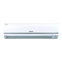
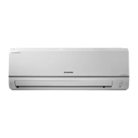
Guidelines for safe and proper indoor unit installation.
Requirements for electrical connections and circuit protection.
Safe operating procedures and precautions for user interaction.
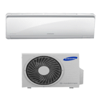
Highlights key features and capabilities of the Multi Inverter series.
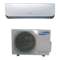
Detailed technical data for various indoor and outdoor unit models.
Comparison of specifications between different development and comparative models.
Lists of optional accessories and their specifications for indoor units.
Lists essential tools required for disassembly and reassembly procedures.
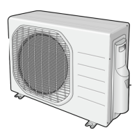
Step-by-step instructions for disassembling and reassembling the outdoor unit.
Explains error codes displayed on indoor units and their causes.
Guides on how to set and configure unit options using the remote control.
Pre-checks and common issues to verify before detailed troubleshooting.
Procedures for installation checks and operational tests.
Diagnosing issues based on observed symptoms and error indicators.
Exploded diagrams and part numbers for various indoor unit models.
Exploded diagrams and part numbers for outdoor units.
Exploded view and parts list for Assy Control Out component.
Identifies components and connectors on indoor unit main PCB.
Identifies components and connectors on outdoor unit main and sub PCBs.
Detailed wiring schematics for various indoor unit models.
Detailed wiring schematics for various outdoor unit models.
Block diagrams illustrating indoor unit circuit functions.
Block diagrams illustrating outdoor unit circuit functions.
Guidelines for choosing an optimal installation location for units.
Procedures for connecting refrigerant pipes and purging air from the system.
Instructions for refilling refrigerant after installation or leakage.
Specifies correct torque values for flare nut connections.
Steps for safely removing refrigerant before servicing or relocation.
Visual representation of the refrigerant flow and components in various models.
Common troubleshooting questions and answers for non-technical issues.
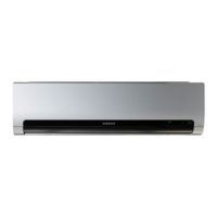
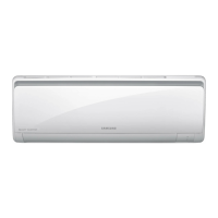
| Indoor unit type | Wall-mountable |
|---|---|
| Indoor unit dimensions (WxDxH) | 820 x 205 x 285 mm |
| Indoor unit noise level (high speed) | 36 dB |
| Outdoor unit dimensions (WxDxH) | 790 x 285 x 545 mm |
| Remotely operated | Yes |
| Cooling capacity (max) | 8500 BTU/h |
| Heating capacity (max) | 11300 BTU/h |
| Air conditioner functions | cooling, heating |
| Cooling capacity in watts (max) | 2500 W |
| Heating capacity in watts (max) | 3300 W |
| Airflow | 474 m³/h |
| Power requirements | 220 - 240V, 50Hz |
| Power consumption (cooling) (max) | - W |