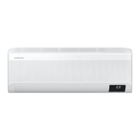
Do you have a question about the Samsung AR12TSFABWKNCV and is the answer not in the manual?
Step-by-step procedures for safely disassembling and reassembling the indoor unit.
Detailed procedures for disassembling and reassembling the N-SI model outdoor unit.
Step-by-step guide for disassembling and reassembling the Outdoor Unit (Q) model.
Detailed procedures for disassembling and reassembling the Outdoor Unit (P) model.
Step-by-step guide for disassembling and reassembling the Outdoor Unit (UB) model.
Provides the electrical schematic showing all wiring connections for the indoor unit.
Presents the electrical schematic detailing all wiring connections for the outdoor unit.
Detailed layout and pin assignments for the indoor unit's main printed circuit board.
Detailed layout and pin assignments for the outdoor unit's inverter printed circuit board.
Explains the functions of each button and display icon on the wireless remote control.
Initial checks to perform before diagnosing potential malfunctions of the air conditioner.
Troubleshooting steps for resolving communication errors between indoor and outdoor units.
Steps to diagnose and fix common compressor starting failures.
Troubleshooting steps for compressor wire connection or rotation issues.
Diagnosing and resolving errors related to current sensors or input current.
Troubleshooting steps for over current protection errors in the unit.
Steps to diagnose why the outdoor unit is not receiving power.
| Energy Efficiency Class | 3 Star |
|---|---|
| Refrigerant | R32 |
| Star Rating | 3 Star |
| Compressor Type | Rotary |
| Noise Level (Outdoor Unit) | 50 dB |
| Operating Temperature | 16-46°C |
| Features | Auto Clean |
| Warranty | 1 Year on Product, 5 Years on Compressor |


 Loading...