EasyManua.ls Logo

Samsung AVXCSH023/032/040CE User Manual

Samsung AVXCSH023/032/040CE
363 pages
To Next Page IconTo Next Page
Page #1 background imageLoading...
Page #1 background image
Refer to the service manual in the GSPN(see the rear cover) for the more information.
AIR CONDITIONER CONTENTS
1. Precautions
2. Product Specifications
3. Disassembly and Reassembly
4. Troubleshooting
5. Exploded Views and Parts List
6. PCB Diagram and Parts List
7. Wiring Diagram
8. Schematic Diagram
9. Reference Sheet
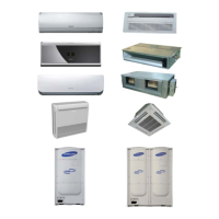
SYSTEM AIR CONDITIONER
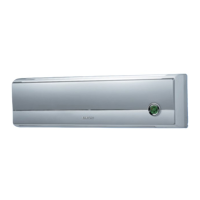
INDOOR UNIT
AVXCSH023/032/040CE
AVXC4H052/072/100/110/145CE
AVXCMH032/040/052/060CE
AVXDSH020/032/040/052/072/100/110/145CE
AVXDUH100/110/145CE
AVXWVH020/032/040/052/060CE
AVXWNH020/032/040/052/060CE
ND023/032/0401HXCA
ND052/072/100/1454HXCA
ND032/040/052/060MHXCA
ND020/032/040/052/072/100/110/145LHXCA
ND100/110/145SHXCA
ND220/280HHXCE(CA)
ND020/032/040/052/060VHXCA
ND020/032/040/052/060NHXCA
ND052/072CHXCA
ND020/032/040/052/060QHXCA
ND052/072/100/110/1454HXCB
OUTDOOR UNIT
RVXVHT075/100/125FE
RD040/050MHXCA
RD075/100/125VHXFA
RD075/100/125VRXFA

Table of Contents

Questions and Answers:

Samsung AVXCSH023/032/040CE Specifications

General IconGeneral
BrandSamsung
ModelAVXCSH023/032/040CE
CategoryAir Conditioner
LanguageEnglish

Summary

Precautions

1-1 Precautions for the Service

Guidelines for safe and correct servicing procedures, including part replacement and harness repair.

1-2 Precautions for the Static Electricity and PL

Measures to prevent static electricity damage to PCBs and safety precautions regarding product handling.

1-3 Precautions for the Safety

Essential safety measures to prevent electric shock, fire, and injury during installation and operation.

1-4 Others

Additional precautions related to refrigerant handling, installation, and general safety.

Product Specifications

2-1 The Feature of Product

Overview of the product's capabilities, including high COP, compact design, and connectivity.

2-2 Product Specifications

Detailed technical specifications for indoor and outdoor units, covering performance, noise, and dimensions.

2-3 Accessory and Option Specifications

Information on available accessories and optional components for system enhancement and functionality.

Disassembly and Reassembly

3-1 Indoor Unit

Step-by-step instructions for disassembling and reassembling various indoor unit components.

3-2 Outdoor Unit

Procedures for safely disassembling and reassembling outdoor unit components.

Troubleshooting

4-1 Setting Option Setup Method

Guide on setting up indoor unit options using the remote controller for correct operation.

4-1-2 Setting an indoor unit address and installation option

Procedures for setting indoor unit addresses and installation options via remote controller.

4-1-3 Option Items

Table detailing various option items and their corresponding settings for different models.

4-2 What to check before diagnosis

Diagnostic steps and LED lamp displays for identifying errors in various indoor unit types.

4-3 How to take measures for each symptom

Detailed guide on troubleshooting symptoms based on error codes and product operation status.

4-4 How to take measures for each symptom

Troubleshooting measures for various indoor unit errors, including sensor and communication issues.

Exploded Views and Parts List

5-1 Indoor Unit

Detailed exploded views and parts list for various indoor unit types.

5-2 Outdoor Unit

Exploded views and parts list for outdoor units, detailing all components and their codes.

PCB Diagram

6-1 Indoor Unit

Detailed PCB diagrams for various indoor unit types, showing component and connector layouts.

6-2 Outdoor Unit

PCB diagrams for outdoor units, illustrating component placement and connections.

Wiring Diagram

7-1 Indoor unit

Wiring diagrams for various indoor unit types, illustrating connections between components.

7-2 Outdoor Unit

Wiring diagrams for outdoor units, showing electrical connections and component layouts.

Schematic Diagram

8-1 Indoor Unit

Schematic diagrams for indoor units, detailing circuit functionality and interconnections.

8-2 Outdoor Unit

Schematic diagrams for outdoor units, illustrating the electrical circuitry and component functions.

Reference Sheet

9-1 Index for Model Name

Guides for decoding model names for indoor and outdoor units based on their codes.

9-2 Refrigerant Circuit Diagram

Diagrams illustrating the refrigerant cycle and function parts for various unit models.

Related product manuals