3-2
3. Disassembly and Assembly
Description Photo Screws
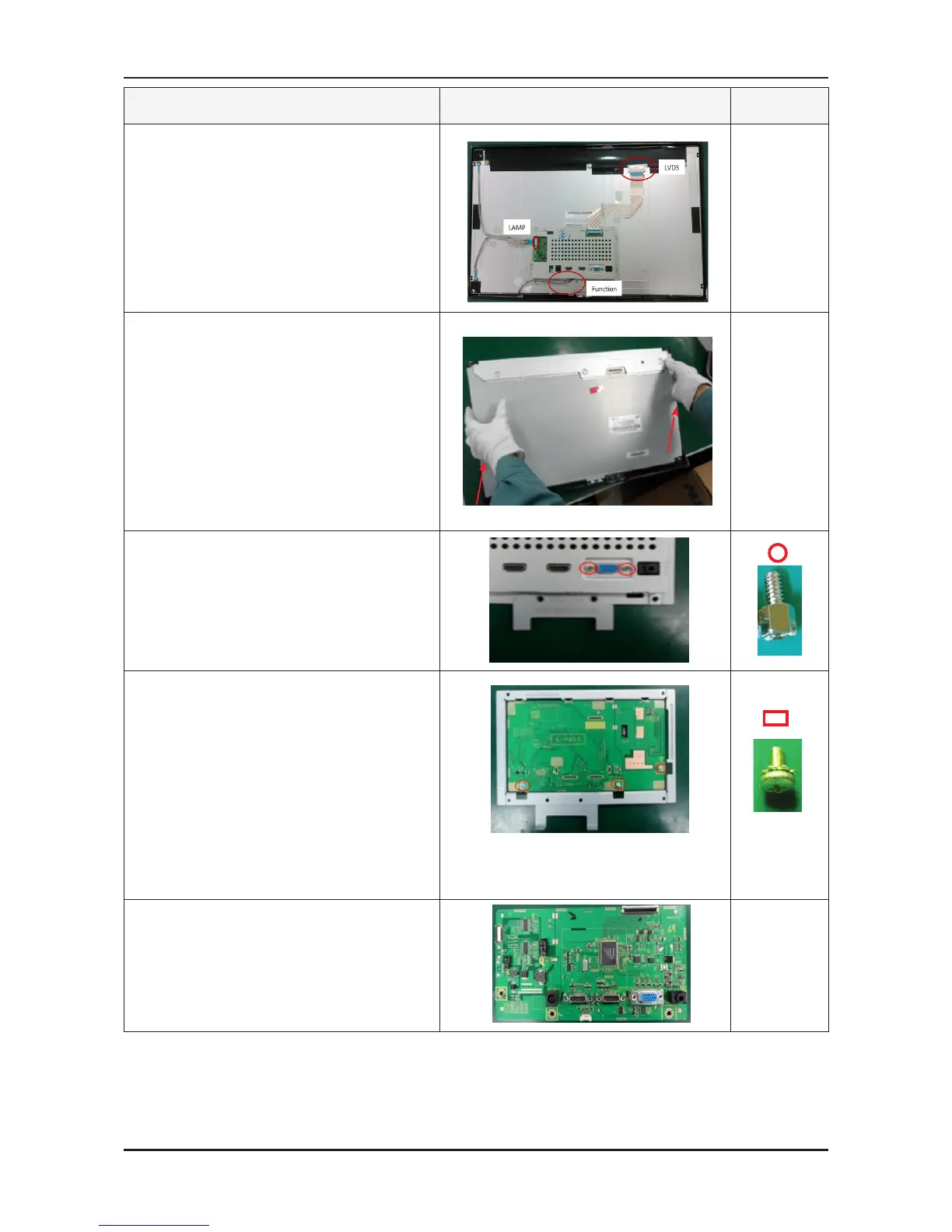
3. Remove the LVDS, LAMP wire, FUNCTION
cable, and then remove
the SHIELD-COVER.
4. Remove the LCD panel.
5. Remove the four (2) screws shown in the gure.
6. Remove the fiive (3) screws shown in the gure
and remove the Bracket support.
7.
Remove the main PCB from the
SHIELD-cover.
※The assembly is in the reverse order of disassembly.




 To Next Page