This document is a service manual for a Samsung microwave oven, model G-643C. It provides comprehensive information for servicing, including specifications, operating instructions, disassembly and reassembly procedures, alignment and adjustments, troubleshooting, exploded views, parts lists, and schematic diagrams.
Function Description
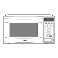
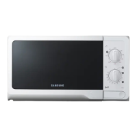
The Samsung G-643C is a microwave oven designed for cooking and heating food. It offers various cooking modes and features to provide flexibility and convenience to the user. The oven utilizes microwave energy for rapid heating and also includes a grill function for browning and crisping.
Important Technical Specifications
- Model: G-643C
- Timer: 99 minutes 90 seconds
- Power Source: 230V 50Hz, AC
- Power Consumption:
- Microwave: 1,350W
- Grill: 1,000W
- Output Power: Adjustable from 80W to 800W (10 level power), following IEC-705 test procedure.
- Specific power levels and corresponding on/off times are detailed:
- 10% (80W): 4 sec on, 26 sec off
- 20% (160W): 7 sec on, 23 sec off
- 30% (240W): 10 sec on, 20 sec off
- 40% (320W): 13 sec on, 17 sec off
- 50% (400W): 16 sec on, 14 sec off
- 60% (480W): 19 sec on, 11 sec off
- 70% (560W): 22 sec on, 8 sec off
- 80% (640W): 25 sec on, 5 sec off
- 90% (720W): 28 sec on, 2 sec off
- 100% (800W): 30 sec on, 0 sec off
- Operating Frequency: 2,450MHz
- Magnetron: OM75SH(31)
- Cooling Method: Cooling fan motor
- Outside Dimensions: 489mm (W) x 275mm (H) x 361mm (D)
- High Voltage Transformer:
- Secondary: Approx. 130Ω
- Filament: Approx. 0Ω
- Primary: Approx. 1.920Ω (at 20°C room temperature)
- Low Voltage Transformer:
- Input (1~2): 1149Ω
- Output 2.9V (4~5): 12.26Ω
- Output 17V (7~8): 2.574Ω
- High Voltage Capacitor: Normal capacitor shows continuity for a short time, then indicates 9MΩ. Shorted capacitor shows continuous continuity. Open capacitor shows constant 9MΩ. Resistance between each terminal and chassis should be infinite.
- High Voltage Diode: Infinite resistance in one direction, several hundred KΩ in the other direction.
Usage Features
The G-643C offers a range of user-friendly features:
- Control Panel: Features dedicated buttons for various functions, including:
- Instant Cook
- Auto Cook/Dish
- Auto Defrost (by Kg/g or lbs/oz)
- Time Cook
- Power Level selection (10 levels)
- Grill
- MWO/Grill Cycle (Combi)
- Memory
- Boost
- Clock Setting
- Timer Setting
- Stop
- Start and Boost
- Display: An 88:88 digital display for time and settings.
- Interior Components: Includes a glass plate (turntable), metal rack (for grill cooking), and guide roller for even cooking.
- Safety Features: Equipped with safety interlock holes and a child lock function (though marked 'X' in the comparison chart, implying it might not be present or is a different implementation).
- Cooking Flexibility: Supports "More/Less" adjustments for cooking time, Auto Cook/Dish, Auto Defrost, Time Cook, Power Level selection, Instant Cook, Memory, and Boost functions.
Maintenance Features
The service manual provides detailed procedures for maintenance and repair:
- Disassembly and Reassembly:
- Magnetron, Motor Assembly, and Lamp: Instructions for removing and replacing the magnetron, cooling fan motor, and oven lamp. Emphasizes careful handling of the magnetron and proper gasket remounting.
- High Voltage Transformer: Procedures for removing the transformer and checking continuity.
- Door Assembly: Detailed steps for removing the door assembly, including hex bolts for hinges. Specific instructions for disassembling Door "C" and Door "E" components, and removing the key door and spring.
- Reassembly Test (Door): Crucial steps to ensure proper door installation, alignment, and microwave leakage testing after door component replacement.
- Fuse Replacement: Instructions for replacing the 10A fuse and troubleshooting if it blows again (checking interlock switches, control circuit board, blower motor, or high voltage transformer).
- Drive Motor Replacement: Steps to replace the turntable drive motor, including removing the glass tray, guide roller, and coupler, and ensuring correct remounting.
- Ceramic Heater Replacement: Procedures for replacing the ceramic heater, including disconnecting connectors and removing securing screws.
- Control Circuit Board (Ass'y Control Box, P.C.B, Window Display & Membrane Panel): Detailed instructions for removing and replacing the control box, printed circuit board (PCB), window display, and membrane panel. Emphasizes grounding to prevent static discharge and careful handling of FPC connectors and adhesive-backed membrane panels.
- Alignment and Adjustments:
- High Voltage Capacitor, Diode, Main Relay, and Power Control Relay: Procedures for checking continuity and resistance of these critical components.
- Primary Switch, Door Sensing Switch, and Monitor Switch: Detailed adjustment procedures for these safety switches, emphasizing replacement of all interlock switches together and ensuring proper gap when the door is closed. Precautionary notes on radiation hazard and using correct part numbers are highlighted.
- Output Power of Magnetron (Water Temperature Rise Test): A standardized test procedure using water to measure the magnetron's output power, ensuring it falls within the normal range (9°C to 11°C temperature rise for 'HIGH' setting). Includes a caution regarding microwave radiation exposure.
- Microwave Heat Distribution (Heat Evenness Test): A test using multiple beakers of water to assess the evenness of microwave heating, with a target distribution rate exceeding 65%.
- Microwave Energy Leakage Measurement: A critical safety procedure using a microwave energy survey meter to check for leakage around the oven, especially the door and seams. The maximum allowable leakage is 5mW/cm², with a target of less than 4mW/cm² after repair.
- Troubleshooting: A comprehensive table listing common symptoms, their potential causes (e.g., open lead wire, defective switches, shorted components, aging magnetron), and corresponding corrections (e.g., adjust switches, replace PCB, tighten screws, consult electrician). Emphasizes safety precautions like grounding, discharging high voltage capacitors, and disconnecting power before checking continuity.
- Parts Lists and Diagrams: Includes exploded views of the oven, detailed parts lists for main components, door parts, control parts, body latch parts, and standard parts, along with their descriptions, quantities, and remarks (e.g., option parts, warning, electrostatically sensitive devices). Schematic diagrams of the PCB and overall electrical system are provided for detailed circuit analysis.