EasyManua.ls Logo

Samsung HPR5052X/XAC User Manual

Samsung HPR5052X/XAC
124 pages
To Next Page IconTo Next Page
Page #1 background imageLoading...
Page #1 background image
PLASMA DISPLAY TV
Chassis : D71C(N_HD_POD_HDMI)_Strauss
Model : HPR5052X/XAC (HP-R5052)
PLASMA DISPLAY TV FEATURES
NTSC/ATSC Tuner Built-In
12-Bit Processing (68.7 Billion Colors)
Split Screen & Picture-In-Picture
Samsung DNIe
(Digital Natural Image engine)
SRS TruSurround XT
1 HDMI Input
Energy Saving
Anynet
System Control Solution
SAMSUNG EPG System
Digital Cable Card Slot
SERVICE
Manual
HP-R5052
Question and Answer IconNeed help?

Do you have a question about the Samsung HPR5052X/XAC and is the answer not in the manual?
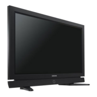
Samsung HPR5052X/XAC Specifications

General IconGeneral
Display TechnologyPlasma
Aspect Ratio16:9
HDMI Ports2
Component Video Inputs2
S-Video Inputs1
Screen Size50 inches
Brightness1500 cd/m²
Input PortsHDMI, Component, S-Video, Composite

Summary

1. Precaution

1-1 Safety Precautions

Instructions to avoid hazards during installation, service, and ESD.

1-2 Servicing Precautions

Guidelines for safe and correct servicing procedures and component handling.

1-3 Static Electricity Precautions

Steps to prevent damage to sensitive components from static discharge.

1-4 Installation Precautions

Safety guidelines for product installation and placement to prevent hazards.

2. Product Specification

2-1 Product Features

Details on the TV's specifications, including block features and chip descriptions.

2-2 Key Features

Comprehensive list of the TV's technical specifications and hardware configuration.

2-3 Specifications Analysis

Comparative analysis of different Samsung TV models' specifications.

2-4 Accessories

List of supplied and optional accessories included with the TV.

3. Alignment & Adjustment

3-1 Service Instruction

Guidelines and procedures for servicing and adjusting the TV after component replacement.

3-2 How to Access Service Mode

Steps to enter the service mode using the remote control and button operations.

3-3 Factory Data

Details on calibration, option bytes, and white balance initial values for factory settings.

3-4 Service Adjustment

Procedures for white balance adjustment, measurement conditions, and methods.

3-5 Software Upgrade

Instructions for downloading boot code and application code for software updates.

3-6 Replacements & Calibration

Procedures for adjusting SMPS panel voltages after component replacement.

4. Exploded View & Part List

4-1 HPR5052X/XAA

Exploded view diagram and part list for the HPR5052X/XAA model.

5. Electrical Part List

5-1 HPR5052X/XAA Service Item

List of electrical parts and their codes for the HPR5052X/XAA model.

6. Troubleshooting

6-1 First Checklist for Troubleshooting

Initial checks and procedures to perform when troubleshooting a TV.

6-2 Checkpoints by Error Mode

Troubleshooting steps for specific error modes like "No Power".

6-3 Troubleshooting Procedures by ASS'Y

Troubleshooting guide for specific assemblies (ASS'Y) and their common symptoms.

7. Block Diagram

7-1 Overall Block Diagram

Overall block diagram illustrating the main components and signal flow of the TV.

7-2 Partial Block Diagram

Partial block diagrams for SMPS, DC-DC SMPS, and driver boards.

8. Wiring Diagram

8-1 Overall Wiring

Diagram showing the overall internal wiring connections between major components.

8-1-1 PDP Module ↔ SMPS Wiring

Wiring connections between the PDP Module and the SMPS.

8-1-2 Main Board ↔ SMPS, Power Button, Function Board, Speaker Out Wiring

Wiring diagram illustrating connections between Main Board and other components.

9. PCB Diagram

9-1 Overall PCB Diagram

Overall PCB layout diagram with numbered component references.

10. Schematic Diagram

10-1 POWER & TUNER

Schematic diagram for the power supply and tuner sections of the TV.

10-2 SOUND-PROCESS

Schematic diagram illustrating the sound processing circuits and audio delay.

10-3 MICOM & IO-EX & AV IN/OUT

Schematic diagram for the MICOM, I/O expansion, and AV input/output connections.

10-4 HDMI & PC

Schematic diagram detailing the HDMI and PC input connections and related circuitry.

10-5 SVP-EX52

Schematic diagram for the SVP-EX52 processing chip and its associated components.

10-6 S3C2800

Schematic diagram for the S3C2800 CPU and related circuitry, including memory interfaces.

10-7 EAGLE+

Schematic diagram for the EAGLE+ MPEG decoder and display clock generator.

10-8 POD

Schematic diagram for the POD (Point of Delivery) module and its power input.

10-9 DNIe Lite & LVDS

Schematic diagram for the DNIe Lite image enhancement and LVDS interface circuits.

10-10 Function A'ssy Board

Schematic diagram for the function assembly board, including buttons and controls.

10-11 Power & IR A'ssy Board

Schematic diagram for the power supply and IR receiver assembly board.

11. Operation Instruction & Installation

11-1 Product Features and Functions

Overview of the TV's front panel features and button functions.

11-1-2 Rear Panel

Description of the rear panel connectors for input and output signals.

11-1-3 Remote Control

Detailed explanation of each button and function on the TV remote control.

11-2 New Features

Explanation of new features like Energy Saving Mode and its operation.

11-2-2 PIP Settings

Table showing Picture-in-Picture (PIP) compatibility across different input sources.

11-3 Installation Notes and Precautions

Important notes and precautions regarding wall bracket installation.

11-3-3 How to assemble the Wall Mount Bracket

Step-by-step instructions for assembling the wall mount bracket.

11-3-4 Fixing the TV panel to the wall attachment panel bracket

Instructions on how to securely attach the TV panel to the wall bracket.

11-3-5 How to Adjust Mounting Angle

Guide on how to adjust the mounting angle of the TV panel.

11-3-6 How to assemble the Stand-Base

Instructions for assembling and attaching the TV stand base.

12. Disassembly & Reassembly

12-1 Overall Disassembly & Reassembly

General notices and procedures for safe disassembly and reassembly of the TV.

12-1-1 Separation of Stand

Steps for removing the TV stand.

12-1-2 Separation of ASSY COVER-STAND CABLE

Procedure for separating the stand cable assembly.

12-1-3 Separation of ASSY COVER P-REAR TOP

Steps for removing the rear top cover assembly.

12-1-4 Separation of ASSY COVER P-REAR

Procedure for removing the rear cover assembly.

12-1-5 Separation of ASSY FAN

Steps for removing the fan assembly.

12-1-6 Separation of ASSY PCB MISC-MAIN

Procedure for removing the main PCB assembly.

12-1-7 Separation of ASSY COVER P-REAR SUB

Steps for removing the rear sub cover assembly.

12-1-8 Separation of ASSY SPEAKER

Procedure for removing the speaker assembly.

12-1-9 Separation of ASSY SMPS, ASSY SMPS POD and ASSY SMPS DC-DC

Steps for removing the SMPS, SMPS POD, and SMPS DC-DC boards.

12-1-10 Separation of ASSY LOGIC BOARD

Procedure for separating the logic board and its flat cable.

12-1-11 Separation of ASSY X DRIVE BOARD

Steps for removing the X Drive Board.

12-1-12 Separation of ASSY Y DRIVE BOARD

Procedure for separating the Y Drive Board and its related Scan Boards.

12-1-13 Separation of ASSY BUFFER BOARD

Steps for removing the buffer boards (TOP and BOT).

13. Circuit Description

13-1 Power ON/OFF Signal Timing Sequence

Timing sequence diagram for the power ON/OFF signals and their flow.

13-2 Partial Block Description

Detailed block descriptions of the main board components and connectors.

13-2-2 Connectors of Main Board

Diagrams and pinouts for various connectors on the main board.

13-2-3 Power Button Board

Description of the power button board components like remote sensor and power button.

13-2-4 Function Key Board

Description of the function key board and its ambient light sensor.

13-2-5 Main SMPS

Diagram and pinouts for the Main SMPS and its various output voltages.

13-2-6 POD SMPS

Block diagram and pinouts for the POD SMPS.

13-2-7 DC-DC SMPS

Diagrams and pinouts for the DC-DC SMPS and its voltage outputs.

13-2-8 PDP Module

Identification of the main boards within the PDP module assembly.

1. Logic Block

Block diagram of the logic board, showing key functional blocks and interfaces.

About Logic Board

Explanation of the logic board's functions and the role of buffer boards.

Major Check Points and Waveforms

Key points for checking operation and reference waveforms for troubleshooting.

1. X, Y Control Block

Drive Circuit Definition

Definition of the drive circuit and its function in pixel control.

Drive Circuit Mechanism

Explanation of how the drive circuit generates waveforms to control PDP pixels.

Drive Circuit Operating Block Diagram

Block diagrams illustrating the operation of the Y and X drive boards.

Drive Circuit Architecture and Function Description

Description of the function of each board in the drive circuit.

Drive Waveform Specifications

Specifications and descriptions of drive waveforms for Y and X components.

Mechanism of the FET Operation and High-Voltage Switching

Explanation of FET operation and high-voltage switching principles.

Drive Board Connector Layout

Connector layout diagram for the X-Main board.

Y-Main

Connector layout diagram for the Y-Main board.

Troubleshooting the Drive Board

Troubleshooting steps for the Y Buffer and checking its operation.

Y Main

Confirmation of Y Main and Y Buffer output using TP points.

Voltage Adjustment Specifications

Specifications for voltage adjustments for Vset, Vs, Vsc_l, Vsc_h, Ve, and Va.

X

Checking the output waveform of the X-Out on the X board.

Attachment 1

Reference waveforms for Y output and Sustain.

Attachment 2

Reference waveforms for X output and Sustain.

13-3 New Circuit Description

13-3-1 Power Saving Modes (Standard, Automatic, Super Power Saving)

Explanation of power saving modes, ambient light sensor, and control mechanisms.

14. Reference Information

14-1 Other issues related to other products

Information on common issues and their resolutions related to various product features.

14-2 Technical Terms

Definitions of technical terms used in the manual.

Related product manuals