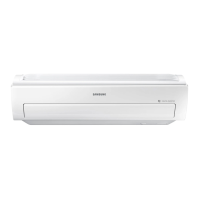
Do you have a question about the Samsung KF-35G/SWA and is the answer not in the manual?
Table detailing specifications for various air conditioner models including cooling capacity, power, and dimensions.
Step-by-step guide for safely disassembling the indoor unit components for maintenance or repair.
Step-by-step guide for safely disassembling the outdoor unit components for maintenance or repair.
Illustrates the path and state changes of the refrigerant within the air conditioning system.
Shows how cooling capacity and power consumption vary with indoor/outdoor temperatures.
Procedure for configuring specific operational settings and features using the remote control.
Lists the option codes required for setting up different model configurations.
Covers initial checks and common issues to diagnose air conditioner malfunctions quickly.
Detailed flowcharts to diagnose problems based on observed symptoms and component behavior.
Diagrams and a list of all parts comprising the indoor unit for identification and ordering.
Diagrams and a list of all parts comprising the outdoor unit for identification and ordering.
Visual representation of the air conditioner's system components and their interconnections.
Schematic showing the electrical connections within the indoor unit of the air conditioner.
Schematic showing the electrical connections within the outdoor unit of the air conditioner.
Detailed electronic circuit diagram for the indoor unit, showing component layout and connections.
| Cooling Capacity | 3.5 kW |
|---|---|
| Power Supply | 220-240V, 50Hz |
| Refrigerant | R410A |
| Power Consumption (Cooling) | 1.0 kW |
| Indoor Unit Weight | 9 kg |
| Air Flow (Indoor) | 550 m³/h |
| Operating Temperature (Cooling) | 18-43 °C |


 Loading...