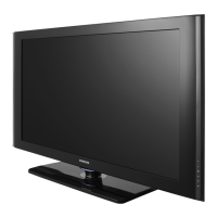
Do you have a question about the Samsung LA40R71B and is the answer not in the manual?
Follow safety, servicing, and ESD precautions to prevent damage and potential hazards.
General guidelines for servicing units covered by this manual.
Follow safety measures during product installation to prevent fire or electric shock.
Highlights design, picture quality, sound, comfort, and ease of use.
Detailed technical specifications for the LA26R71B model.
Compares key features across different TV models.
General instructions for adjusting and calibrating the LCD TV.
Procedures to access and use service modes for adjustment.
Procedures for calibrating white balance and adjusting color parameters.
Overview of main functional blocks with IP board.
Detailed block diagram of the main processing unit.
Description and block diagrams of the SMPS board.
Initial steps for diagnosing and resolving common issues.
Diagnostic flowcharts for specific error conditions.
Troubleshooting steps for audio problems.
Visual diagram showing the assembly of the LA26R71B TV.
List of part numbers and descriptions for the LA26R71B model.
Visual assembly diagram for LA32R71B/LA32R71W models.
List of part numbers and descriptions for the LA40R71B model.
Detailed list of electrical components for LA26R71B.
Detailed list of electrical components for LA32R71B.
Detailed list of electrical components for LA40R71B.
Schematic showing interconnections between main components.
Detailed pinout definitions for main board and speaker connectors.
Diagram illustrating connections on the power supply board.
Schematic diagram for the power supply and sound sections.
Schematic showing input and output connector pin assignments.
Schematic diagram illustrating the Micom (microcontroller) circuit.
| Screen Size | 40 inches |
|---|---|
| Display Type | LCD |
| Brightness | 500 cd/m² |
| Response Time | 8 ms |
| HDMI Ports | 2 |
| Component Video Inputs | 1 |
| Composite Video Inputs | 1 |
| Aspect Ratio | 16:9 |
| Resolution | 1366 x 768 pixels |
| Audio Output | 20 W |
| Viewing Angle | 178°/178° |
| Input Ports | HDMI, Component, Composite, PC Input |
| Sound Output | 20W |


