Do you have a question about the Samsung LE23R86BD and is the answer not in the manual?
Essential safety measures to follow before and during servicing the LCD monitor.
Precautions to be taken by service technicians when working on the LCD monitor.
Techniques to reduce component damage caused by static electricity.
Safety precautions related to product installation and ventilation.
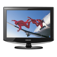
Highlights key design and feature aspects of the TFT-LCD TV.
Detailed specifications for the LE23R86BD model.
Compares specifications across different TV models for user convenience.
Lists available optional accessories for the TV models.
General instructions for performing installation and touch-up adjustments.
Procedure to enter and navigate the factory or service mode.
Details on factory calibration, option tables, and other service data.
Methods for adjusting white balance and other picture settings.
Instructions for updating the TV's flash ROM with new software.
Initial checks for common troubleshooting issues like cable connections and power.
Diagnostic steps for specific error modes like 'No Power' or 'No Video'.
Exploded diagram showing the assembly of the LE23R86BD model.
List of part codes and specifications for the LE23R86BD model.
Detailed list of electrical parts for the LE23R86BDX model.
Detailed wiring diagram illustrating connections between boards and components.
Layout diagram of the main board, showing component and connector positions.
Detailed pin descriptions for key connectors like the main board power supply.
Diagram showing the physical location of connectors on the PCB.
Schematic diagram of the power supply section.
Schematic diagram for the sound processing circuitry.
Schematic diagram for input/output jacks including HDMI and PC.
Schematic diagram for other input/output jacks like SCART and AV.
Schematic diagram detailing the MICOM (microcontroller) circuit.
Schematic diagram for the SVP-UX scaler IC and related components.
Schematic diagram for the DDR memory and tuner sections.
Schematic diagram for DTV reset signals and AV output circuitry.
Schematic diagram for DTV memory and STi5105 chipset.
Schematic diagram for PCMCIA interface and STi5105.
Schematic diagram for the dimming board.
Glossary of technical terms used in the manual.
Detailed pin assignments for various connectors like DVI, Component, S-Video, etc.
Provides timing charts for LCD panel modes and supported resolutions.
Information describing different LCD panels used in the models.
Highlights key design and feature aspects of the TFT-LCD TV.
Detailed specifications for the LE23R86BD model.
General instructions for performing installation and touch-up adjustments.
Procedure to enter and navigate the factory or service mode.
Details on factory calibration, option tables, and other service data.
Methods for adjusting white balance and other picture settings.
Instructions for updating the TV's flash ROM with new software.
Initial checks for common troubleshooting issues like cable connections and power.
Diagnostic steps for specific error modes like 'No Power' or 'No Video'.
Exploded diagram showing the assembly of the LE23R86BD model.
List of part codes and specifications for the LE23R86BD model.
Exploded diagram showing the assembly of the LE26R86BD model.
List of part codes and specifications for the LE26R86BD model.
Exploded diagram showing the assembly of the LE32R86BD model.
List of part codes and specifications for the LE32R86BD model.
Exploded diagram showing the assembly of the LE37R81BX model.
List of part codes and specifications for the LE37R81BX model.
Exploded diagram showing the assembly of the LE37R86BD model.
List of part codes and specifications for the LE37R86BD model.
Exploded diagram showing the assembly of the LE37R81BX model.
List of part codes and specifications for the LE37R81BX model.
Exploded diagram showing the assembly of the LE40R86BD model.
List of part codes and specifications for the LE40R86BD model.
Exploded diagram showing the assembly of the LE40R81BX model.
List of part codes and specifications for the LE40R81BX model.
Detailed list of electrical parts for the LE23R86BDX model.
Detailed list of electrical parts for the LE26R86BDX model.
Detailed list of electrical parts for the LE32R86BDX model.
Detailed list of electrical parts for the LE37R81BX model.
Exploded diagram showing the assembly of the LE40R86BD model.
List of part codes and specifications for the LE40R86BD model.
Exploded diagram showing the assembly of the LE37R81BX model.
List of part codes and specifications for the LE37R81BX model.
Exploded diagram showing the assembly of the LE40R81BX model.
List of part codes and specifications for the LE40R81BX model.
Detailed wiring diagram illustrating connections between boards and components.
Layout diagram of the main board, showing component and connector positions.
Detailed pin descriptions for key connectors like the main board power supply.
Diagram showing the physical location of connectors on the PCB.
Details of output connectors including AC Input, S, and A.
Schematic diagram of the power supply section.
Schematic diagram for the sound processing circuitry.
Schematic diagram for input/output jacks including HDMI and PC.
Schematic diagram for other input/output jacks like SCART and AV.
Schematic diagram detailing the MICOM (microcontroller) circuit.
Schematic diagram for the SVP-UX scaler IC and related components.
Schematic diagram for the DDR memory and tuner sections.
Schematic diagram for DTV reset signals and AV output circuitry.
Schematic diagram for DTV memory and STi5105 chipset.
Schematic diagram for PCMCIA interface and STi5105.
Schematic diagram for the dimming board.
| Screen Size | 23 inches |
|---|---|
| Resolution | 1366 x 768 |
| HD Type | HD Ready |
| Aspect Ratio | 16:9 |
| Contrast Ratio | 3000:1 |
| Brightness | 500 cd/m² |
| Response Time | 8 ms |
| Speakers | 2 x 5W |
| HDMI Ports Quantity | 2 |
| Viewing Angle | 178° (horizontal), 178° (vertical) |
| Input Ports | 1 x Component, 1 x Composite, 1 x PC |