Do you have a question about the Samsung LE27S71B and is the answer not in the manual?
Follow safety, servicing, and ESD precautions to prevent damage and hazards.
Warning about electrolytic capacitor polarity; read safety precautions before servicing.
ESD precautions for handling sensitive devices to prevent damage.
Safety measures for installing the TV.
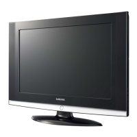
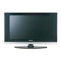
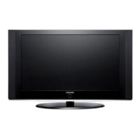
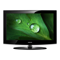
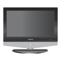
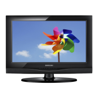
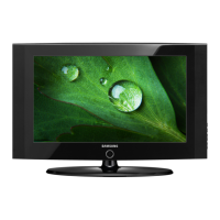
Highlights key aesthetic and performance features of the TV.
Detailed technical specifications for the LE27S71B model.
Detailed technical specifications for the LE32S71B model.
Detailed technical specifications for the LE37S71B model.
Detailed technical specifications for the LE40S71B model.
Comparison of specifications across different TV models.
List of optional accessories and their part codes.
General guidelines for performing service adjustments and calibration.
Instructions for entering the TV's service or factory mode.
Lists various factory data settings, including Calibration, Option Table, White Balance, SVP-FX, and Adjust.
Details on performing service adjustments like white balance calibration and adjustment.
Instructions on how to update Flash ROM using Flash Downloader.
Initial troubleshooting steps involving cable connections, power input, and voltage checks.
Diagnostic checkpoints for troubleshooting common error modes like "No Power".
Troubleshooting flowchart for "No Video" issues when using an Analog PC input.
Troubleshooting flowchart for "No Video" issues with HDMI input.
Troubleshooting flowchart for "No Picture" issues when using Tuner/CVBS input.
Troubleshooting flowchart for "No Picture" issues with Video_CVBS input.
Troubleshooting flowchart for "No Picture" issues with S-Video input.
Troubleshooting flowchart for "No Sound" issues.
Exploded view diagram showing the assembly of the LE27S71B model.
List of parts for the LE27S71B model, including location, code, item name, quantity, and remarks.
Detailed list of electrical components for the LE27S71B model, organized by level and location.
Continuation of electrical parts list, detailing connectors and diodes.
Continuation of electrical parts list, detailing resistors.
High-level block diagram of the TV's main functional blocks and signal flow.
Wiring diagram for the main board, showing connector pin assignments for various models.
Layout diagram of the main board, indicating the location of major components and connectors.
Pin characteristics for CN800 (Main Board power supply) and CN600/CN601 (Speaker Connector).
Pin assignments for the CN503 connector, which carries LVDS signals for the LCD panel.
Pin definitions for the CN801 AC input connector.
Pin definitions for the CN802 connector, related to inverter power supply and panel dimming.
Schematic diagram illustrating the power and sound sections of the TV.
Schematic diagram showing SCART, Component, PC, HDMI, and AV input connections.
Schematic diagram of the Micom (microcomputer) block, including main and sub-micom sections.
Schematic diagram for SVP-PX, PX-Power, and LBE-Option blocks, detailing signal processing.
Diagram of the TV's front panel, identifying controls like Source, Menu, Volume, and Power.
Diagrams illustrating the rear and side panel connections for different TV sizes.
Diagram and explanation of the remote control buttons and their functions.
Step-by-step instructions for attaching the TV stand.
Information on installing a wall mount kit, advising to check separate instructions.
Procedures for disassembling the TV, emphasizing safety precautions for ESD components and cabinet removal.
Reassembly procedures are the reverse of disassembly procedures.
Diagram showing the layout of the main PCB for a 26-inch model.
Diagram showing the layout of the main PCB for 32", 37", and 40-inch models, with key ICs labeled.
Image of the 26-inch SMPS (Switching Mode Power Supply) board.
Image of the 40-inch IP (Inverter/Power) Board.
Overview of the TV's main functional blocks: Main board, IP board, and T-con board.
Detailed block diagram of the SVP-PX line-up, showing signal flow from inputs to outputs.
Block diagram of the SMPS board for 26"/32" models, detailing power stages.
Glossary of technical terms used in the manual, such as TFT-LCD, ADC, PLL, Inverter, and AC Adapter.
Pin details for various connectors like DVI-D, Component, S-Video, D-SUB, SCART.
Timing specifications for LCD panel and supported PC modes.
Table listing panel manufacturers, vendor P/N, panel code, panel ABB, sticker code, and remarks.
| Screen Size | 27 inches |
|---|---|
| Resolution | 1366 x 768 |
| Contrast Ratio | 3000:1 |
| Brightness | 500 cd/m² |
| Response Time | 8 ms |
| Aspect Ratio | 16:9 |
| Power Consumption | 120 W |
| HD Format | 720p (HD Ready) |
| Viewing Angle | 178° (horizontal), 178° (vertical) |
| Input Ports | HDMI, Component, Composite, S-Video |