Do you have a question about the Samsung LE32S71B and is the answer not in the manual?
Essential safety guidelines for handling the TV and preventing electrical hazards.
Key precautions to follow before and during TV servicing to ensure safety and prevent damage.
Measures to prevent static discharge damage to sensitive electronic components.
Safety guidelines for installing the TV to prevent fire hazards and ensure proper ventilation.
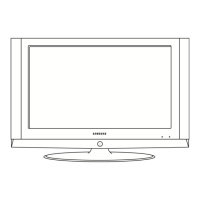
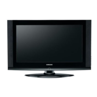
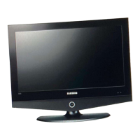
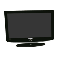
Highlights the TV's design features and perceived quality aspects like slim design and picture quality.
Detailed technical specifications for the LE27S71B model, including panel, resolution, and power.
Detailed technical specifications for the LE32S71B model, covering panel, resolution, and power consumption.
Detailed technical specifications for the LE37S71B model, including dimensions and environmental considerations.
Detailed technical specifications for the LE40S71B model, covering panel size, power, and sound.
Side-by-side comparison of specifications for different TV models, highlighting key differences.
List of optional accessories available for the TV, including part numbers and remarks.
General guidelines for TV installation adjustments and use of test equipment.
Steps to enter the service mode using remote control sequences and function keys.
Information on factory calibration, option tables, and various adjustment parameters.
Detailed procedures for service adjustments, focusing on white balance calibration and settings.
Instructions for installing and performing a software upgrade via Flash ROM.
Basic checks for common TV issues like cable connections, power input, and voltage.
Diagnostic steps for specific error modes such as 'No Power' and 'No Video'.
Troubleshooting guide for 'No Video' issues specifically related to Analog PC input.
Troubleshooting steps for 'No Video' problems when using the Digital HDMI input.
Troubleshooting steps for 'No Picture' issues related to Tuner and CVBS inputs.
Troubleshooting guide for 'No Picture' problems using the Video (CVBS) input.
Troubleshooting steps for 'No Picture' issues when using the S-Video input.
Troubleshooting steps for 'No Sound' problems, checking audio signals and connections.
Diagram showing the exploded view of the LE27S71B model and its components.
List of all parts for the LE27S71B model with their respective codes and specifications.
Diagram showing the exploded view of the LE32S71B model and its components.
List of all parts for the LE32S71B model with their respective codes and specifications.
Diagram showing the exploded view of the LE37S71B model and its components.
List of all parts for the LE37S71B model with their respective codes and specifications.
Diagram showing the exploded view of the LE40S71B model and its components.
List of all parts for the LE40S71B model with their respective codes and specifications.
Detailed list of electrical components and parts for the LE27S71B model.
Detailed list of electrical components and parts for the LE32S71B model.
Detailed list of electrical components and parts for the LE37S71B model.
Detailed list of electrical components and parts for the LE40S71B model.
Overall block diagram illustrating the main functional blocks and their interconnections.
Wiring diagrams for various TV models including LE27S71B, LE32S71B, LE37S71B, LE40S71B.
Diagram showing the physical layout of the main board and its connectors.
Pin assignments and functions for key connectors like CN800 and CN600/CN601.
Details on pin assignments for Front Control (CN221) and Panel Control (CN501) connectors.
Pin assignments for the LVDS signal connector (CN503).
Diagram showing the physical layout of the power board and its connectors.
Pin details for AC Input (CN801), Main Board Power (CN801), and Panel Control (CNM804).
Pin definitions for Inverter Power Supply connectors CN802 and CN803.
An alternative view or diagram of the Power Board layout.
Alternative pin assignments for AC Input (CN801), Main Board Power (CN801), and Panel Control (CNM804).
Alternative pin definitions for Inverter Power Supply connectors CN803 and CN804.
Schematic diagrams for the power supply and sound sections of the TV.
Schematic showing input signal paths like SCART, HDMI, PC, and AV.
Schematic diagram detailing the Micom (microcontroller) circuits.
Schematics for SVP-PX, PX-Power, and LBE-Option blocks.
Schematics related to specific applications like DDR, Tuner, FRC, and Function.
Description of the TV's front panel buttons and indicators.
Diagrams showing the rear and side panel connections for various input/output ports.
Explanation of buttons and functions on the TV's remote control.
Instructions for installing the TV stand and the wall mount kit.
Step-by-step instructions for safely disassembling the TV, including cautions.
Instructions for reassembling the TV in the reverse order of disassembly.
Diagram of the main PCB for 26-inch models, showing component locations.
Diagrams of the main PCB for 32", 37", and 40" models, highlighting key ICs.
Diagram of the Switched-Mode Power Supply (SMPS) board for 26-inch models.
Diagram of the Switched-Mode Power Supply (SMPS) board for 32-inch models.
Diagram of the IP (Interface/Power) Board for 40-inch models.
Overview of the TV's main functional blocks: Main board, IP board, and T-con board.
Detailed block diagram of the SVP-PX line-up, showing signal flow and key components.
Block diagrams for SMPS boards (26", 32") illustrating power stages.
Alternative block diagrams for SMPS boards (26", 32") showing power flow.
Block diagrams for SMPS boards (37") illustrating power stages.
Block diagrams for IP boards (32", 40") showing power and CCFL control.
Definitions of technical terms used in the manual, covering display and signal technologies.
Pin assignments for DVI-D, S-Video, Component, A/V, D-SUB, SCART (1&2), and PC display modes.
Timing specifications for LCD panel modes, detailing horizontal and vertical signal parameters.
Details on panel models, vendor codes, panel codes, and associated remarks.
| Screen Size | 32 inches |
|---|---|
| Resolution | 1366 x 768 |
| Display Type | LCD |
| HD Format | HD Ready |
| Contrast Ratio | 5000:1 |
| Brightness | 500 cd/m² |
| Response Time | 8 ms |
| HDMI Ports | 2 |
| Component Video Inputs | 1 |
| Composite Video Inputs | 1 |
| Aspect Ratio | 16:9 |
| Sound Output | 10W x 2 |
| Viewing Angle | 178° |
| Input Ports | HDMI, Component, Composite, PC Input |