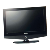
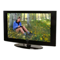
This document is a service manual for the Samsung TFT-LCD TV/MONITOR, specifically models Chassis VR17JO and Model LT17N23W. It provides comprehensive information for servicing, troubleshooting, and maintaining the device.
The manual outlines the following key sections:
- Precautions: Essential safety guidelines to ensure safe handling and servicing of the device.
- Product Specifications: Detailed technical specifications of the TFT-LCD TV/MONITOR.
- Disassembly & Reassembly: Instructions for taking apart and putting back together the device, crucial for repairs and component replacement.
- Alignment & Adjustments: Procedures for calibrating and fine-tuning various aspects of the TV/MONITOR to ensure optimal performance.
- Troubleshooting: A guide to diagnosing and resolving common issues, including flowcharts and waveform examples.
- Exploded View & Parts List: Diagrams showing the device's components and a list of all replaceable parts.
- Parts List: A comprehensive list of all components with their respective part numbers.
- Block Diagram: A high-level overview of the device's electronic architecture.
- Wiring Diagram: Detailed schematics showing the interconnections between different components.
- PCB Layout: Diagrams illustrating the physical arrangement of components on the Printed Circuit Boards.
- Schematic Diagrams: Detailed circuit diagrams for various sections of the device.
- Panel Description: Information specific to the LCD panel used in the TV/MONITOR.
Function Description:
The Samsung TFT-LCD TV/MONITOR (Chassis VR17JO, Model LT17N23W) serves as a dual-purpose display device, functioning as both a television and a computer monitor. This versatility allows users to enjoy broadcast television content and connect to a computer for productivity or gaming. The device incorporates TFT-LCD technology for display, offering a compact and relatively lightweight design compared to older display technologies.
Important Technical Specifications (Derived from context, not explicitly stated in a single section):
While specific numerical values for screen size, resolution, or refresh rate are not directly provided in the table of contents, the manual implies several technical aspects:
- Display Technology: TFT-LCD (Thin-Film Transistor Liquid Crystal Display).
- Input Capabilities: The troubleshooting and wiring diagrams suggest a wide range of input options, including:
- Tuner Input: For receiving broadcast television signals (TV).
- AV CVBS Input: Composite video input, common for older video devices.
- S-Video Input: A higher-quality analog video input compared to composite.
- Component Input (Y, Pb, Pr): For higher-definition analog video signals, supporting resolutions like 408i, 480p, 720p, and 1080i.
- D-Connector Input: Likely referring to a D-sub (VGA) connector for PC input.
- PC Audio Input: Separate audio inputs for PC connection.
- Headphone Output: For private listening.
- Speaker Output: For integrated or external speakers.
- Power Supply: The troubleshooting section mentions checking for proper DC 14V and 5V, indicating the device operates on these DC voltages, likely supplied by an external adapter. It also refers to a 14V inverter, suggesting the use of backlighting that requires an inverter circuit.
- Internal Components: The block diagram and schematic diagrams reveal the presence of various integrated circuits (ICs) such as IC101, IC102, IC103, IC305, IC565 (PW565), IC601, IC602, IC603, IC604, IC605, IC607, IC608, IC610, IC701, IC703, and IC702 (TDA7050T/N3 for audio). These ICs handle functions like signal processing, power management, and audio amplification.
- Control System: The device includes a main board (BN91-00716A) and a sub-board (CN809) that manage overall operations.
- Audio System: Features an audio amplifier (IC702) and speaker outputs (SPKOUTL+, SPKOUTL-, SPKOUTR+, SPKOUTR-), indicating integrated stereo sound capabilities.
- User Interface: Includes LED indicators (LED GRN, LED RED) and an IR receiver for remote control (REMOCON BN59-00374A).
Usage Features:
- Multi-Input Support: The wide array of video and audio inputs allows the device to connect to various sources, from traditional TV antennas and VCRs to modern DVD players, game consoles, and personal computers.
- Remote Control Operation: The inclusion of a remote control (REMOCON) simplifies user interaction and navigation through menus and settings.
- Factory Mode Adjustments: The manual details how to enter and navigate the "Factory Mode" using specific remote control key sequences (POWER OFF -> MUTE -> 1 -> 8 -> 2 -> POWER ON, or PICTURE ON -> DISPLAY -> FACTORY). This mode provides access to advanced calibration and service adjustments, including:
- Calibration: For fine-tuning display parameters.
- Option Table: To configure specific device options (e.g., LNA, Melody Volume, DATA).
- Color Control: Adjustments for Sub-Brightness, Sub-Contrast, Red/Green/Blue Offset, Red/Green/Blue Gain, Brightness, and Contrast.
- PW565: Adjustments for Red/Green/Blue Gain and Offset.
- VPC3230-MAIN: Configuration of various video processing parameters (CT, BR, ACC_SAT, TINT, SATCb, SATCr, CIPTNT, CIPBR, CIPCT, PFS, PK, VPK, LPF2, CBW2, CBW, IFC, LILVL, LDLY, PKCOR).
- ADC: Adjustments for Red/Green/Blue Gain and Offset, Pr/Y/Pb Gain and Offset, Current, and VCO.
- Test Pattern: Selection of various test patterns (Luma Ramp 16/128 step, White 16/240, Color Bar, RGB Ramp 32 step) for display testing and calibration.
- Service Adjust: Including Pilot High and Pilot Low settings.
- Reset: To initialize data in the MICOM.
- Power Indicator: An LED indicator signals the power status (green for on).
Maintenance Features:
The manual is primarily a maintenance guide, offering extensive features for servicing:
- Troubleshooting Flowcharts: Step-by-step diagnostic procedures for common issues like "No Power," "No PC Signal," "No Video (Tuner, AV CVBS, S-Video)," "No Video (Component 1, D Connector Input)," and "No Sound." These flowcharts guide technicians through checks (e.g., voltage measurements, signal presence) and suggest corrective actions (e.g., check adapter, change ICs, replace main board, replace cables, replace speakers).
- Waveform Examples: For each troubleshooting step involving signal checks, corresponding oscilloscope waveforms are provided. These visual references (e.g., 1-1 to 1-7 for "No Power," 2-1 to 2-5 for "No PC Signal," 3-1 to 3-9 for "No Video," 4-1 to 4-2 for "No Sound") are critical for technicians to compare measured signals against expected patterns, aiding in precise fault identification.
- Parts Replacement Guidance: The troubleshooting steps frequently recommend replacing specific ICs, boards (main board, SUB_board), or cables, indicating modular design for easier repairs.
- Detailed Diagrams:
- Wiring Diagram: Shows connector pinouts (e.g., CN505, CN806, CN807, CN804, CN805, CN806, CN808, CN809, CN701, CN702) and signal names (e.g., TXOUT, GND, ADJ_BRIGHTNESS, AGASW_INVERTER, LED GRN/RED, A3.3V, IR, KEY1, POWER_KEY, CH+_OUT, CH-_OUT, IDENT_HP, HP_L/R, PC_AUDIO_L/R, SVHS_C/Y, VIDEO_CVBS, VIDEO_L/R, COMP1_L/R, D4_Y/PB/PR, PC_RED/GREEN/BLUE, H_SYNC, V_SYNC, DDC_TXO/RXO, 14V_INVERTER, SPKOUTL/R+/-). This is essential for tracing signals and verifying connections.
- Schematic Diagrams: Provide detailed circuit layouts, component values, and interconnections, allowing for in-depth analysis and component-level repair.
- Block Diagram: Offers a high-level functional overview, helping to understand the signal flow and identify problematic sections.
- PCB Layout: Shows the physical location of components on the circuit boards, facilitating component identification and replacement.
- General Alignment Instructions: Emphasizes the importance of correct impedance matching, avoiding overload, and using specified test equipment. It also includes safety warnings such as disconnecting power before replacing parts and using an isolation transformer.
- White Balance Adjustment: Detailed procedures for adjusting white balance at high and low light levels, including setting 'Y' values, red/blue offsets, and red/blue gains, with reference to Toshiba ABL Patterns.
- PW565 and VPC3230-MAIN Data: Provides default data values for these critical video processing sections, which are fixed and not adjustable by the user, serving as reference for technicians.
- ADC Adjustment: Instructions for adjusting Red/Green/Blue Gain and Offset, Pr/Y/Pb Gain and Offset, Current, and VCO to match the basic level of DTV and PC input signals.
- Parts List: A comprehensive list of all replaceable parts with their code numbers (e.g., ASSY PCB MAIN BN94-00492A, LCD-PANEL BN07-00119A, REMOCON BN59-00374A), enabling easy ordering of replacement components. The manual also directs users to an online CMS website for updated part codes.
- MICOM Program Version: The "Check sum" and "T_VIC17NJP_1018 07/05/2003 18:12:26" entries in the factory mode indicate the firmware version and build date, which can be important for software-related diagnostics or updates.
This service manual is an indispensable resource for technicians involved in the repair and maintenance of the Samsung TFT-LCD TV/MONITOR LT17N23W, providing all necessary information from high-level overviews to detailed circuit diagrams and troubleshooting steps.