Do you have a question about the Samsung LW20M21CP and is the answer not in the manual?
Follow safety, servicing, and ESD precautions to prevent damage and hazards.
General guidelines for safe servicing, including capacitor polarity and general precautions.
Precautions to prevent component damage caused by static electricity.
Precautions for safely installing the product, including handling and ventilation.
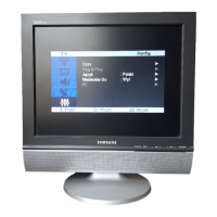
Key features of the TFT-LCD TV, including remote control and menu system.
Detailed technical specifications for the LW15M23CP model.
Detailed technical specifications for the LW17M24CP model.
Detailed technical specifications for the LW20M21CP model.
Comparison of specifications across different TV models.
List of optional accessories and their specifications.
General instructions for servicing, including test equipment and connections.
Procedures for entering the service mode using remote control keys.
Overview of factory data adjustments like DLC/MWE, SFR, Sub Adjust, etc.
Procedures for service adjustments, including EDID input and Micom upgrade.
Initial checks for troubleshooting, including cable connections and power input.
Troubleshooting steps categorized by error modes like No Power.
Troubleshooting steps for 'No Picture' issues across different inputs.
Troubleshooting steps for 'No Sound' issues.
Exploded view and parts list for the LW15M23CP model.
Exploded view and parts list for the LW17M24CP model.
Exploded view and parts list for the LW20M21CP model.
Detailed list of electrical components for the LW15M23CP model.
Detailed list of electrical components for the LW17M24CP model.
Detailed list of electrical components for the LW20M21CP model.
Diagram showing wiring connections on the main PCB.
Schematic diagram for the input power and sound sections.
Schematic diagram for the UOC III section.
Schematic diagram for the output scaler and LVDS connections.
Schematic diagram for the IP board of the LE15S51BP model.
Schematic diagram for the IP board of the LE20S51BP model.
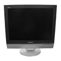
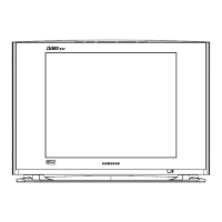
Overview of the product's front features and controls.
Description of the front panel controls and indicators.
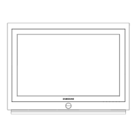
Diagram showing rear panel connections and ports.
Explanation of the remote control buttons and their functions.
Notes and precautions related to product installation.
Instructions for connecting various external devices like aerials, VCRs, computers.
Instructions for using the Kensington lock for security.
Information on the retractable stand's tilt and swivel features.
Instructions for installing VESA compliant mounting devices.
Steps for installing the wall mount kit for specific models.
Details on angle adjustments for different mounting configurations.
Step-by-step guide for disassembling the LW15M23CP model.
Step-by-step guide for disassembling the LW17M24CP model.
Step-by-step guide for disassembling the LW20M21CP model.
Procedure for replacing the lamp assemblies.
General procedures for reassembling the unit.
Top view layout of the main PCB with component labels.
Layout of the power board for LW15M23CP, LW17M24CP, and LW20M21CP models.
Overall block diagram of the TV's circuit structure.
Power tree diagram for the main board.
Wiring diagram showing connector pin assignments on the main board.
Pin assignments for LVDS, TLL, and Power interface connectors.
Definitions of technical terms used in the manual.
Pin assignments for Scart, S-Video, A/V, and D-SUB connectors.
Timing chart for computer-generated video signals.
Preset timing modes for computer signal compatibility.
Description of various LCD panels used in the models.