Alignment and Adjustments
4-3Samsung Electronics
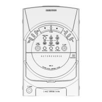
1) Connect the measuring instruments as shown in Figure 4-6.
2) Set the DOLBY NR Switch off.
3) Measuring tape:
MTT-5512 (or equivalent: normal recording)
4) The input signals supply 400Hz 400mV into AUX IN of AMP (AUDIO OSC.)
4-2-3 To Adjust Recording Level
Normal
electric
current
for
recording
1
2
See diagram
for adjustment
locations
See diagram
for adjustment
locations
400 mV
6 mV
Connect to TP2
as in Figure4-6
and read VTVM
L-CH : JSR3L
to the right and
left.
R-CH : JSR3R
to the right and
left
L-CH: JSR4L and
R-CH: JSR4R to
the right and left
To Adjust
Standard
Remark
Pre-Setup
Item
Step
Pre-Setup
Condition
Connect to
TP3 as in Figure
4-6 and read the
VTVM
Insert MTT-5512
into Deck2, then
press REC button.
Insert MTT-5512 into
Deck2, then press
REC button.
BIAS
Electric
current
Figure 4-6
Audio OSC.
Cassette Deck
Oscilloscope
AUX IN
LINE OUT
VTVM
IN
TP
IN OUT
NOTES