Do you have a question about the Samsung MAX-888 and is the answer not in the manual?
Safety, servicing, and ESD precautions to prevent damage and hazards.
Precautions specific to servicing the unit.
Techniques to reduce component damage from static electricity.
Precautions and warning labels for laser products.
Instructions for removing and reattaching the cabinet top.
Procedures for disassembling the CD mechanism and door.
Steps to remove the rear cabinet and main PCB.
How to detach the front cabinet and bottom panel.
Detailed disassembly of the CD mechanism components.
Steps for disassembling the CD deck assembly.
Alignment and adjustment procedures for the tuner section.
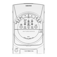
Alignment and adjustment steps for the cassette deck.
Procedure for adjusting the recording level of the cassette deck.
Description of the RF amplifier block and its components.
Description of the tracking error amplifier circuit.
Explanation of the focus OK circuit operation.
Description of the mirror circuit and its function.
Explanation of the EFM comparator circuit.
Description of the defect detection circuit.
Description of the APC circuit for laser diode control.
Description of the AGC stability circuit.
Description of the post filter circuit.
Description of the center voltage generation circuit.
Overview of the servo block functions.
Description of the sled servo block.
Description of the spindle servo block.
Troubleshooting specific to the amplifier section.
Troubleshooting steps for cases where there is no audio output.
Troubleshooting for FM/AM tuner issues.
Troubleshooting steps for tape deck malfunctions.
Troubleshooting specific to the CD player functionality.
Troubleshooting guide for audio output problems.
Exploded views and parts list for the cassette deck.
Exploded views and parts list for the main unit.
Part list for MAX-870 model.
Part list for MAX-880 model.
Exploded views and parts list for the CD mecha.
Exploded views and parts list for the optional CD mecha.
Exploded views and parts list for the CD deck.
Exploded views and parts list for the optional CD deck.
Exploded views and parts list for the speaker system.
Block diagram of the main processing and control unit.
Block diagram illustrating the CD mechanism and control circuitry.
Internal diagrams for specific ICs and transistors.
Block diagram for the TDA7439 audio processing IC.
Block diagram for the BA3834S IC.
Block diagram for the LA1836 tuner IC.
Block diagram for the NJM074 audio amplifier IC.
Block diagram for the HA12203/HA12204 audio processing IC.
Block diagram for the NJU3716M IC.
Block diagram for the motor driver ICs.
Block diagram for the KS9286 digital signal processor.
Block diagram for the KB9223 servo processor.
Pinout and function list for the µ-COM controller UIC1.
Continued pinout and function list for the µ-COM controller UIC1.
Pinout and function list for the NJU3718 IC.
Detailed list of ports and their functions for the NIC9223.
Detailed list of ports and their functions for the NIC9286.
Visual layout of the main PCB components.
Component layout and labels for the main PCB.
PCB diagram for the front panel.
PCB diagram for the deck mechanism.
PCB diagram for the CD unit.
PCB diagram for the CD SUB board.
Schematic diagram of the main circuit board.
Schematic diagram of the front panel circuitry.
Schematic diagram of the deck mechanism circuitry.
Schematic diagram of the CD unit circuitry.
| Brand | Samsung |
|---|---|
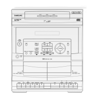
| Model | MAX-888 |
| Category | Stereo System |
| Language | English |