Do you have a question about the Samsung MAX-940 and is the answer not in the manual?
Describes adjustments for the tuner section of the component system.
Exploded views and parts list for the cassette deck.
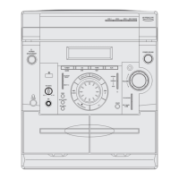
Overall exploded view and parts list for the entire unit.
Electrical parts list for MAX909/910/916 models.
Block diagram of the main common part of the system.
Printed circuit board layout for the main common part.
PCB layout for the front part of MAX909/910/916 models.
Common wiring diagram showing interconnections between major units.
Schematic diagram for the common CD part.
Schematic diagram for the common main part.
Schematic diagram for the common tuner section.
| Brand | Samsung |
|---|---|
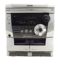
| Model | MAX-940 |
| Category | Stereo System |
| Type | Mini Hi-Fi System |
| Number of Discs | 3 |
| Tuner | FM/AM |
| Frequency Response | 20Hz - 20kHz |
| Signal-to-Noise Ratio | 80dB |
| Playable Media | CD, CD-R/RW |