EasyManua.ls Logo

Samsung MAX-N25 - User Manual

Samsung MAX-N25
28 pages
Print Icon
To Next Page IconTo Next Page
Loading...
3 CD CHANGER
MINI MINI COMPONENT
MAX-N25
SERVICE
Manual
MINI COMPONENT SYSTME CONTENTS
Standby
R
Mono/ST
TUNER CD TAPE AUX
Band
Disc 1
CD Repeat Disc Change
Open/Close
Disc 2 Disc 3
Vol.
Hi Speed
Dubbing
Program/Set
Phones
AI Off/Sleep
Timer On/Off Timer/Clock
Demo
S.BASS
Down Preset/Manual Up
C
l
a
s
s
i
c
R
o
c
k
P
o
p
CD Synchro /
1. Alignment and Adjustments
2. Exploded Views and Parts List
3. Electrical Parts List
4. Block Diagrams
5. PCB Diagrams
6. Wiring Diagram
7. Schematic Diagrams
Question and Answer IconNeed help?

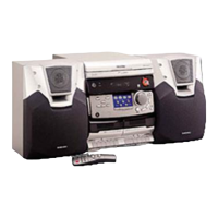
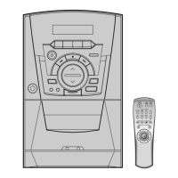
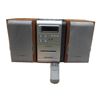
Do you have a question about the Samsung MAX-N25 and is the answer not in the manual?

Summary

Alignment and Adjustments

Tuner Alignment and Calibration

Details FM, AM/MW I.F, and FM THD adjustments, including specific test points and settings.

Cassette Deck Adjustments

Covers tape speed, record frequency, azimuth, and bias voltage calibration procedures.

Exploded Views and Parts Lists

Main Unit Exploded View and Parts

Provides an exploded view and parts list for the main unit.

Deck and Speaker Parts Lists

Lists components for the cassette deck, CD deck, and speaker assemblies.

Electrical Parts List

Comprehensive Component Inventory

Detailed list of electrical components with codes, specifications, and remarks.

Block Diagrams

Main Part Block Diagram

Illustrates functional blocks and signal flow for the main unit.

CD Section Block Diagram

Shows functional blocks and signal flow for the CD playback section.

Printed Circuit Board Diagrams

Main PCB Layout

Diagram showing component placement on the MAIN printed circuit board.

Front PCB Layout

Diagram showing component placement on the FRONT printed circuit board.

CD PCB Layout

Diagram showing component placement on the CD parts printed circuit board.

Tuner PCB Layout

Diagrams detailing component placement for LW and SW tuner boards.

Wiring Diagram

System Interconnection Diagram

Illustrates wiring connections between the main, front, tape deck, tuner, and CD PCBs.

Schematic Diagrams

CD Section Schematic

Detailed schematic of the CD playback circuitry.

Main Part Schematic

Detailed schematic of the main unit's electronic circuits.

Front Part Schematic

Detailed schematic of the front panel and control circuitry.

Tuner Section Schematic

Detailed schematic of the FM, AM, LW, and SW tuner circuitry.

Samsung MAX-N25 Specifications

General IconGeneral
BrandSamsung
ModelMAX-N25
CategoryStereo System
TypeMini Hi-Fi System
Number of Discs1
Playable MediaCD, CD-R, CD-RW
Audio Output ModeStereo
Frequency Response20Hz - 20kHz
Signal-to-Noise Ratio80 dB
Input Sensitivity500mV
Tuner BandsFM, AM
Weight4.5 kg

Related product manuals