Do you have a question about the Samsung NS140HHXEA and is the answer not in the manual?
Essential safety guidelines for proper installation of the air conditioner.
Details on safe power connection and circuit breaker requirements.
Important safety instructions for operating the air conditioner.
Environmental guidelines for proper disposal of the unit and its components.
Additional safety considerations and general operating notes.
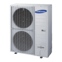
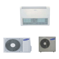
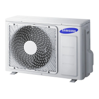
Overview of key features and benefits of the air conditioner models.
Detailed technical specifications including dimensions, capacity, power, and noise levels.
List of included accessories, their codes, and relevant specifications.
Step-by-step instructions for disassembling and reassembling the indoor unit components.
Step-by-step instructions for disassembling and reassembling the outdoor unit components.
Guide to configuring indoor unit addresses and installation options via the wired remote controller.
Procedure for setting specific option codes for the indoor unit using the remote controller.
Information on indoor unit LED error indicators and troubleshooting steps.
Details on outdoor unit display error codes and diagnostic procedures.
Common checks and initial troubleshooting steps before diagnosing deeper issues.
Comprehensive guide for diagnosing faults based on specific symptoms and error codes.
Diagrams and part numbers for indoor unit components, organized by model.
Diagrams and part numbers for outdoor unit components, organized by model.
Exploded view and parts list for the control output assembly.
Detailed diagram and component identification for the indoor unit's main PCB.
Detailed diagrams and component identification for various outdoor unit PCBs (Main, Inverter, EMI).
Wiring schematics for indoor units, illustrating connections between components.
Wiring schematics for outdoor units, detailing connections for various PCBs and components.
Circuit schematic diagrams for the indoor unit's main PCB.
Circuit schematic diagrams for outdoor unit PCBs including SMPS, DC LINK, PFC, IPM, etc.
Diagram illustrating the refrigerant flow and key components in the cooling/heating cycle.
Code breakdown and interpretation guide for outdoor and indoor unit model names.
Graphs showing pressure variations based on outdoor and indoor temperatures in different modes.
| Brand | Samsung |
|---|---|
| Model | NS140HHXEA |
| Category | Air Conditioner |
| Language | English |