Do you have a question about the Samsung RF24J9960S4/AA and is the answer not in the manual?
Precautions for electrical repairs, part replacement, and general safety.
Guidelines for safe installation location, grounding, and storing items.
Safety guidelines and precautions before performing disassembly procedures.
Step-by-step guide for removing the refrigerator door.
Step-by-step guide for removing the freezer doors.
Procedures for removing the main control board and inverter PCB.
Instructions for installing the CO2 cylinder and using sparkling water functions.
Explains the functions and operation of the main control panel buttons.
Covers Energy Saving, Door Alarm, and Control Panel Lock features.
Operation of Power Cool, Sparkling Level, and Maker functions.
Explains functions used for diagnosing operational failures.
Guides for performing self-diagnosis on the appliance.
Detailed list and explanation of self-diagnostic error codes.
Explains how load conditions are displayed on the control panel.
Details on Cooling Off, AP Mode, and E-Smart functions.
Guides for configuring appliance options and reference tables.
Step-by-step guides for resolving specific operational symptoms.
Identifies components and connectors on the main printed circuit board.
Shows component placement and connector positions on the inverter PCB.
Wiring diagram for models with sparkling water and dispenser features.
Common issues and solutions to check before contacting service.
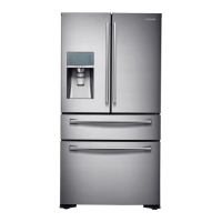
| Type | French Door |
|---|---|
| Refrigerator Capacity | 15.7 cu. ft. |
| Ice Maker | Yes |
| Water Dispenser | Yes |
| Energy Star Certified | Yes |
| Color | Stainless Steel |
| Door Alarm | Yes |
| Adjustable Shelves | Yes |
| Convertible Compartment | Yes |
| Wi-Fi Enabled | Yes |
| SmartThings Compatible | Yes |
| Dimensions (W x H x D) | 35 3/4" x 71 7/8" x 34" |