Do you have a question about the Samsung RH25H5613SL/CL and is the answer not in the manual?
Explains the meaning of various warning and caution symbols used in the manual.
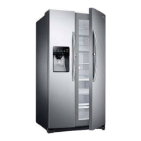
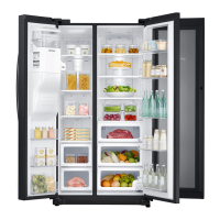
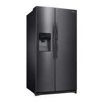
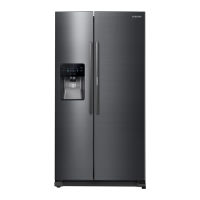
Details key features like Twin Cooling Plus, Multi Airflow, and LED Tower Lighting.
Presents detailed specifications for different models, including capacity, dimensions, and electrical ratings.
Details safety precautions and tools required before disassembling the refrigerator.
Explains how to activate and cancel pull-down, defrost, and cancellation modes using button combinations.
Covers self-diagnostics during initial power-on and normal operation, including error codes and cancellation.
Lists items, descriptions, display indicators, and digital numbers for failure diagnosis modes.
A flowchart to diagnose issues when there is no power at the Inverter or Main PCB.
A flowchart to diagnose power supply issues specifically for the Inverter PBA.
A troubleshooting guide for diagnosing compressor non-operation issues, checking sensors and signals.
A flowchart to troubleshoot defrosting failures, checking sensors, heaters, and defrost sensor temperature.
Explains how errors are displayed for defective sensors and provides troubleshooting steps for ambient and humidity sensors.
Addresses issues with continuous alarm sounds, including "DingDong" and "Beeping" sounds, and their causes.
Guides on troubleshooting abnormal operation of the Panel PBA, including display issues and button functionality.
Provides a troubleshooting process for when the compressor or other fans are not operating, checking voltages.
Troubleshoots issues with ice dispensing, including crushed and cubed ice, checking switches, motors, and connections.
A troubleshooting guide for ice maker failures, checking water supply, sensor unit, and PBA.
Outlines steps to diagnose and fix issues related to ICE water not being supplied, checking valves and PBA.
Details troubleshooting steps for when water is not supplied to the dispenser, checking valves and dispenser switch.
Provides a troubleshooting flowchart for the ice route motor, checking its proper operation and selected modes.
Presents temperature tables with corresponding voltage and resistance values for sensor diagnostics.
Explains LED blinking patterns related to compressor protecting functions like starting failure, voltage errors, and motor lock.
| Brand | Samsung |
|---|---|
| Model | RH25H5613SL/CL |
| Category | Refrigerator |
| Language | English |